


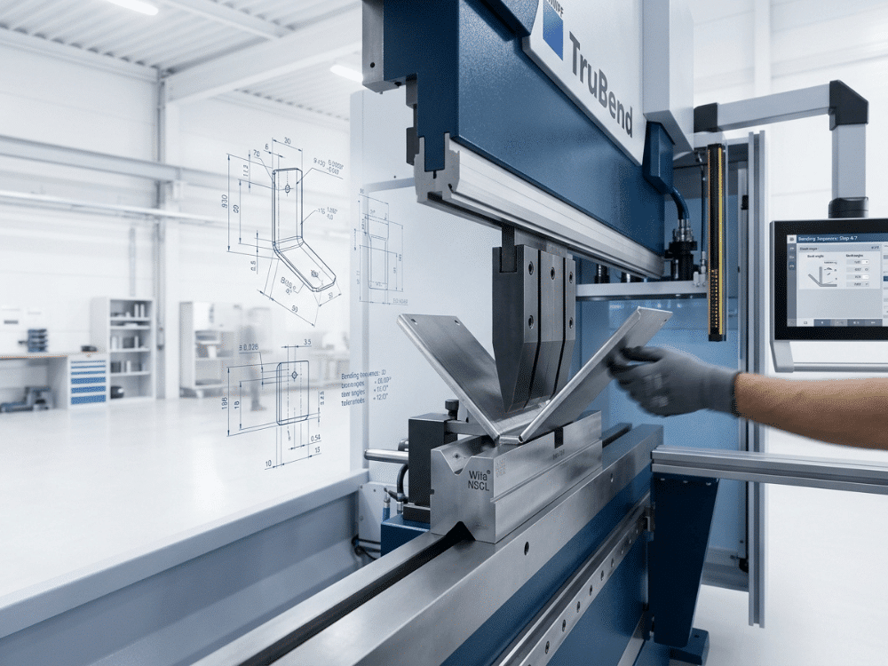

Sheet metal bending is a metal fabrication process that uses a press brake to form sheet metal into angular shapes without material removal. Good bending outcomes depend on correct minimum bend radius, K-factor, bend allowance calculations, and DFM-compliant geometry. Rules of thumb exist, but all critical tolerances should be confirmed with your fabricator.
Sheet metal bending sounds straightforward. You push a flat blank against a die, apply force, and the metal forms a new angle. But a significant percentage of bending projects reach the shop floor with design errors that cause cracking, springback, distorted holes, or scrapped parts—problems that a DFM review could have caught in minutes.
This guide covers the full picture: how material behavior and press brake mechanics influence your bend, which design rules reduce risk, how to calculate bend allowance and K-factor, and where common defects come from. You’ll also find a practical DFM checklist and comparison tables to support faster decision-making.
All formulas and guidelines presented here are starting references and rules of thumb. Actual tolerances, minimum radii, and tonnage requirements depend on your specific material grade, thickness, temper, tooling, and supplier capabilities. Always confirm critical dimensions with your fabricator before finalizing a design.
What Is Sheet Metal Bending?
Sheet metal bending is a forming process that plastically deforms a flat metal sheet along a linear axis to create angular features—flanges, channels, brackets, enclosures, and more. A press brake applies force through a punch and die set, bending the sheet to a defined angle without cutting or removing material.
The process is widely used across aerospace, automotive, electronics, and industrial enclosure manufacturing because it combines geometric flexibility with high repeatability and relatively low tooling cost.
How Does Material Behavior Affect Sheet Metal Bending?
The way a material responds to bending determines your minimum radius, springback allowance, and risk of cracking.
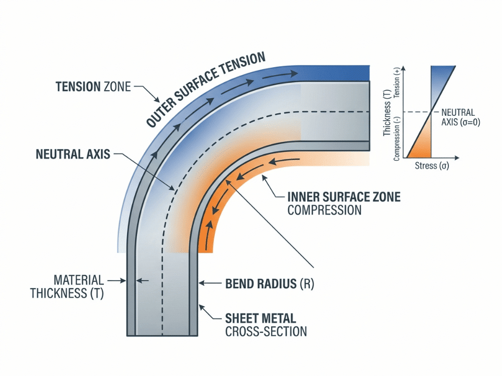
When metal bends, the outer surface experiences tension while the inner surface experiences compression. Between these two zones sits a theoretical neutral axis—a layer that neither stretches nor compresses. This neutral axis location is captured by the K-factor (explained in detail below).
Key material behaviors to understand:
- Elastic vs. plastic deformation. All bending starts elastic (the metal wants to spring back). To hold a permanent shape, the bend must push the material past its yield strength into plastic deformation. This is why springback must be compensated by overbending.
- Springback. After the press brake releases pressure, the part partially returns toward its original shape. Springback magnitude depends on yield strength, elastic modulus, bend radius, and thickness. High-strength materials such as stainless steel 304 and 6061-T6 aluminum exhibit greater springback than mild steel or annealed copper.
- Work hardening. During plastic deformation, the material’s yield strength increases in the bend zone. This is generally beneficial for part strength but can reduce ductility in subsequent forming operations.
- Grain direction. Sheet metal has a rolling direction from the mill process. Bending perpendicular to the grain direction (across the grain) generally allows tighter radii. Bending parallel to the grain increases the risk of cracking, especially in harder tempers. For crack-sensitive materials like 6061-T6 aluminum, orienting bends perpendicular to the grain direction is strongly recommended.
Material families and general bendability:
- Mild steel (low carbon): High ductility, forgiving radii, low springback. Generally the most bend-friendly metal.
- Stainless steel 304: Moderate-to-high work hardening, significant springback, requires greater overbend compensation.
- Aluminum 5052-H32: Good bendability for aluminum. Commonly used in sheet metal applications.
- Aluminum 6061-T6: Lower ductility due to heat treatment. Prone to cracking at tight radii, especially when bent parallel to the grain. Use larger radii and confirm with the fabricator.
- Copper and brass: Generally ductile and easy to bend. Annealed grades offer tighter possible radii.
- Titanium: High springback, requires significant overbend. Confirm all bend parameters with your fabricator.
How Does a Press Brake Work?
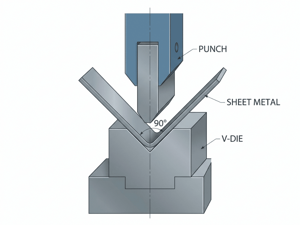
A press brake uses a punch (upper tool) that presses the sheet into a V-die (lower tool), forming a bend at the intended angle. The key variables are tonnage (bending force), bend sequence, and springback compensation.
What is the tonnage needed for sheet metal bending?
A commonly used rule-of-thumb formula for estimating press brake tonnage is:
Tonnage ≈ (575 × T² × L) / V
Where:
- T = material thickness (inches)
- L = bend length (inches)
- V = V-die opening width (inches)
- 575 is an empirical constant for mild steel
This formula provides a rough starting estimate. Harder materials (stainless steel, high-strength aluminum) require multiplication by a material factor—typically 1.4–1.7× for stainless, and 0.5–0.7× for soft aluminum. Actual tonnage requirements should always be calculated or confirmed by your fabricator, as geometry, tooling selection, and material variations significantly affect the result.
How does springback affect bending accuracy?
Springback causes the part to open slightly after the press brake releases. To compensate, the operator overbends the material beyond the target angle. The amount of overbend required varies by material, radius-to-thickness ratio, and bend method. Springback compensation is typically dialed in through test bends at the shop level.
Why does bend sequence matter?
On complex parts with multiple bends, the order of operations determines whether each subsequent bend is physically accessible. Poor sequence planning can make certain bends impossible without specialized tooling. Designing with sequence in mind—and discussing it with your fabricator during DFM review—prevents costly rework.
Press Brake Tooling and Die Selection
Punch and die selection directly affects achievable bend radii, surface quality, and required tonnage.
- Standard acute punches (30°–60°): Used for tight-angle bends and hemming.
- Gooseneck punches: Designed to clear flanges on U-shaped or box profiles.
- Swan-neck/offset punches: Used for step bends or offset bends.
- Standard V-dies: The most common lower tooling. V-die opening is typically 6–10× material thickness for air bending.
- Bottoming/coining dies: Used when tighter tolerances or sharper radii are required. These require significantly higher tonnage than air bending.
- Radius dies: Used to achieve specific inside radii rather than leaving the radius tool-dependent.
- Custom tooling: Available for non-standard profiles. Adds cost and lead time; justify only for high-volume or geometry-critical applications.
Types of Sheet Metal Bending
|
Bending Method |
Description |
Radius Control |
Tonnage |
Typical Use |
|---|---|---|---|---|
|
Air bending |
Sheet contacts only punch tip and die edges |
Moderate (tool-dependent) |
Low |
Most common; versatile |
|
Bottom bending |
Sheet pressed to die floor |
Good |
Medium |
Better angle consistency than air bending |
|
Coining |
Material compressed fully into die |
Excellent |
Very high |
Tight tolerances, sharp radii |
|
Roll bending |
Sheet passed through three rollers |
Radius-defined |
Variable |
Cylinders, cones, arcs |
|
Wipe bending |
Sheet wiped over a die edge |
Moderate |
Medium |
Edge flanges, hem prep |
|
Rotary bending |
Rotating tool forms the bend |
Good |
Low-medium |
Reduces marking; good for coated materials |
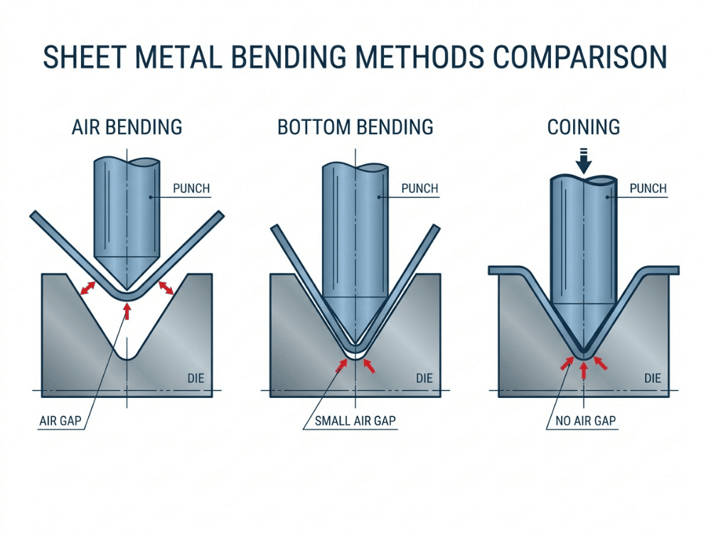
Air bending is the default process at most fabrication shops. It requires less tonnage than bottoming or coining and gives operators flexibility to form different angles with the same die set by adjusting the stroke depth. The tradeoff is somewhat less angle consistency, which is why tolerances of ±1° are typical for air-bent parts unless tighter control is specified.
Sheet Metal Bending Design Guidelines
Following these guidelines during design reduces fabrication issues and rework before a single part is made.
All values below are starting references. Confirm specific limits with your fabricator based on your material, thickness, and tooling.
What is the minimum bend radius for sheet metal?
As a general rule of thumb, the minimum inside bend radius for most materials is approximately 1× the material thickness (1T). However, this varies considerably:
- Mild steel: 0.5T–1T is often achievable
- Stainless steel 304: 1T–1.5T is a common starting point
- Aluminum 5052-H32: ~1T
- Aluminum 6061-T6: 3T–4T or more depending on temper and grain direction; cracking risk is elevated at tighter radii
Using the largest inside radius your design allows reduces tonnage requirements, extends tooling life, and lowers the risk of cracking.
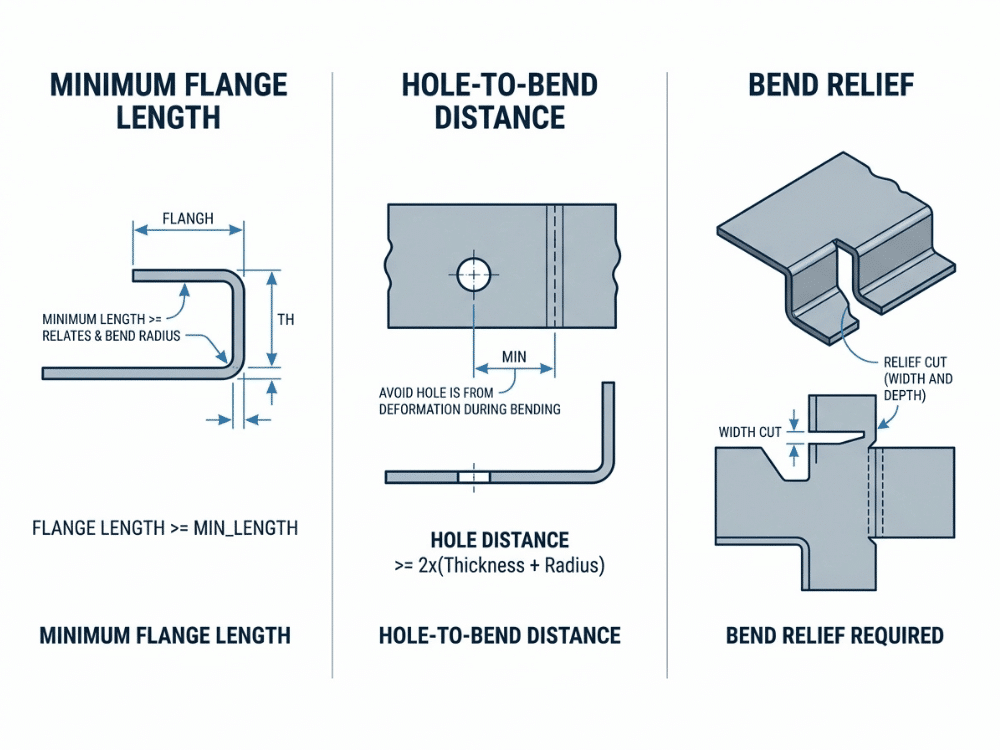
What is the minimum flange length for sheet metal bending?
Flanges that are too short can’t be gripped by the press brake tooling. As a rule of thumb, the minimum flange length is approximately 4× the material thickness (4T), or about 3 mm, whichever is greater. Short flanges are a common DFM issue—check this before sending drawings.
How far should holes be from a bend line?
Placing holes too close to a bend causes them to deform. A commonly used guideline: keep holes at least 2.5× material thickness + bend radius away from the bend line. Slots and cutouts need even more clearance. If your design requires holes closer to the bend, add bend relief cuts, or move the hole to a flat section.
What is bend relief, and when is it needed?
Bend relief is a small notch cut at each end of a flange at the point where the bend line meets the adjacent geometry. Without bend relief, tearing or distortion can occur at the corners. As a starting guideline, relief width should be at least 1T and relief depth at least 1T + bend radius. Your fabricator can confirm the specific relief dimensions for your tooling.
How should you handle multiple bends on one part?
- Consistent inside radius: Use the same inside radius across all bends on a part where possible. Mixing radii forces multiple die changes and increases cost.
- Bend-to-bend spacing: Maintain sufficient distance between adjacent parallel bends so the sheet can seat in the die without interference from a prior bend.
- Symmetrical bend sequences: Design symmetrically where possible to simplify setup and reduce fixturing requirements.
What tolerances are achievable with sheet metal bending?
Typical achievable tolerances for air-bent parts are approximately:
- Angle: ±0.5°–±1°
- Flat dimensions: ±0.1–±0.25 mm (material and thickness dependent)
- Flange length: ±0.25–±0.5 mm
Tighter tolerances require bottoming or coining and should be discussed with your fabricator during DFM review.
Bend Allowance, Bend Deduction, and K-Factor Explained
These three values determine how much flat material is consumed by a bend—getting them right ensures your flat pattern cuts out at the correct dimensions.
What is K-factor in sheet metal bending?
The K-factor represents the position of the neutral axis within the material thickness during bending:
K = t / T
Where:
- t = distance from the inside face to the neutral axis
- T = total material thickness
A K-factor of 0.5 means the neutral axis is exactly at the center of the material. In practice, the neutral axis shifts toward the inside of the bend. Typical K-factor values:
- Soft materials (annealed copper, soft aluminum): ~0.35–0.40
- Mid-range materials (mild steel, 5052 aluminum): ~0.40–0.45
- Hard or high-strength materials: ~0.45–0.50
K-factor values are empirical. Many fabricators have material-specific K-factor tables derived from test bends.
How do you calculate bend allowance?
Bend allowance (BA) is the arc length of the material at the neutral axis through the bend:
BA = π × (R + K × T) × (A / 180)
Where:
- R = inside bend radius
- K = K-factor
- T = material thickness
- A = bend angle (degrees)
What is bend deduction?
Bend deduction (BD) is the amount subtracted from the total flat length to account for the material consumed in the bend zone:
BD = 2 × (R + T) × tan(A/2) − BA
Worked example
- Material: Mild steel, T = 2 mm
- Inside radius: R = 2 mm
- Bend angle: A = 90°
- K-factor: 0.44
BA = π × (2 + 0.44 × 2) × (90/180) = π × 2.88 × 0.5 = 4.52 mm
BD = 2 × (2 + 2) × tan(45°) − 4.52 = 2 × 4 × 1 − 4.52 = 8 − 4.52 = 3.48 mm
If your design software supports K-factor input (SolidWorks, CATIA, Fusion 360, etc.), entering a verified K-factor will automatically produce accurate flat patterns. Always validate flat pattern dimensions against fabricator data for critical parts.
Materials and Their Bendability
|
Material |
Relative Bendability |
Notes |
|---|---|---|
|
Mild steel (1018/A36) |
Excellent |
High ductility, low springback, forgiving radii |
|
Stainless steel 304 |
Moderate |
Higher springback; overbend compensation required |
|
Stainless steel 316 |
Moderate |
Similar to 304; slightly lower work hardening |
|
Aluminum 5052-H32 |
Good |
Popular sheet metal alloy; reasonable bend radii |
|
Aluminum 6061-T6 |
Challenging |
Cracking risk at tight radii; bend perpendicular to grain; use generous radii |
|
Copper (C110 annealed) |
Excellent |
Very ductile; tight radii achievable |
|
Brass (C260) |
Good-Excellent |
Ductile; springback lower than steel |
|
Titanium (Grade 2) |
Moderate |
High springback; confirm bend parameters with fabricator |
A note on 6061-T6 aluminum: This is one of the most commonly over-tightened materials in sheet metal designs. Its T6 heat treatment significantly reduces ductility compared to annealed aluminum. Cracking at inside bend radii below 3T–4T is a real risk, especially when bending parallel to the rolling direction. If bend radius is critical, consider switching to 5052-H32, which offers much better formability. If 6061-T6 is required for structural reasons, use generous radii and confirm orientation and tooling with your fabricator.
A note on stainless steel 304: Stainless steel 304 work-hardens rapidly during bending, which increases its strength in the bend zone but also increases springback. Angle tolerances of ±1° are common for air-bent SS304; tighter angles require bottoming or coining.
Common Bending Defects and How to Fix Them
|
Defect |
Likely Cause |
Fix |
|---|---|---|
|
Cracking at bend |
Radius too tight; wrong grain direction; low ductility material temper |
Increase inside radius; orient bend perpendicular to grain; use annealed temper |
|
Springback / angle error |
Insufficient overbend compensation |
Adjust overbend; switch to bottoming if tighter tolerance required |
|
Hole distortion |
Hole too close to bend line |
Move hole ≥ 2.5T + R from bend; add bend relief |
|
Bow/warp along flange |
Residual stress in material; unsupported long flanges |
Use backstop; adjust clamping; check material flatness |
|
Scratching / marking |
Die edge condition; no urethane pad |
Use radius die; urethane pad on die; clean tools |
|
Short flange failure |
Flange too short to grip |
Redesign flange to ≥ 4T minimum |
|
Tearing at notch corners |
No bend relief or insufficient relief |
Add bend relief at flange termination; size to ≥ 1T wide × 1T + R deep |
Sheet Metal Bending vs. Other Fabrication Processes
|
Process |
Geometric Output |
Material Removal? |
Tooling Cost |
Volume Suitability |
Typical Tolerance |
|---|---|---|---|---|---|
|
Sheet metal bending |
Angles, flanges, channels |
No |
Low |
Low to high |
±0.1–±0.5 mm |
|
CNC machining [internal link: CNC machining service] |
Complex 3D profiles |
Yes |
Low-medium (no hard tooling) |
Low to medium |
±0.01–±0.05 mm |
|
Laser cutting [internal link: laser cutting service] |
2D flat profiles |
Yes (thermal) |
Low |
Low to high |
±0.1–±0.2 mm |
|
Stamping [internal link: stamping service] |
High-volume flat/formed parts |
Partial |
High |
High only |
±0.05–±0.2 mm |
|
Roll forming |
Continuous profiles |
No |
Medium-high |
High |
±0.2–±0.5 mm |
When Should You Choose Sheet Metal Bending?
Sheet metal bending is the right choice when:
- You need angular or channel profiles from flat sheet stock at low-to-medium volumes
- Tooling cost must stay low (no hard dies required)
- Part geometry consists primarily of bends, flanges, and holes rather than complex 3D profiles
- Weight reduction matters—sheet metal is inherently thin-walled
- Quick iteration is needed, since setup and changeover times are short
Sheet metal bending is less suitable for very tight flatness tolerances over long spans, complex 3D contoured surfaces (where CNC machining is better), or extremely high volumes, where stamping is more cost-efficient.
How Essengold Supports Sheet Metal Bending Projects
Essengold’s manufacturing team handles sheet metal bending projects from prototype stage through production, providing DFM feedback before your order enters the production queue.
What Essengold’s bending capability covers:
- Materials: Mild steel, stainless steel (304, 316), aluminum alloys (5052, 6061), copper, and brass in a range of standard sheet thicknesses
- Tolerances: Typical angular tolerances of ±0.5°; flat dimension tolerances from ±0.1 mm depending on geometry and material (confirm for your specific part)
- DFM review: Essengold’s engineering team reviews submitted drawings for minimum bend radius compliance, hole-to-bend clearance, flange length, bend relief requirements, and flat pattern accuracy before production begins
- Prototyping to production: Single prototypes, small development runs, and scalable production quantities are all supported
- Surface finishing: Anodizing, powder coating, plating, and passivation available post-bending
To submit your drawing for a quote and DFM review, upload your files via the Essengold contact/quote page or email sales@essengoldparts.com. Include your material specification, required thickness, bend tolerances, and any notes on critical features.
Ready to get your bending project reviewed? Submit your drawings to Essengold’s engineering team for a free DFM check and quote — before tooling is cut. Get a quote →
DFM Checklist for Sheet Metal Bending
Use this checklist before sending drawings to your fabricator. It won’t catch every issue—design reviews with your fabricator will—but it eliminates the most common causes of rework.
Geometry
- Inside bend radius ≥ 1T for mild steel; ≥ 3T–4T for 6061-T6 aluminum
- Flange length ≥ 4T (or ≥ 3 mm, whichever is larger)
- Holes and slots ≥ 2.5T + R from all bend lines
- Bend relief added at all flange terminations adjacent to adjacent faces
- Consistent inside radius used across all bends on the part
- Bend sequence reviewed for accessibility on multi-bend parts
Flat Pattern
- K-factor input matches material and radius (confirmed with fabricator)
- Bend allowance and flat dimensions verified by calculation or test bend
- Flat pattern reviewed for interference between bends
Tolerances
- Angular tolerances are ≥ ±0.5° for air bending, or bottoming/coining specified if tighter
- Critical dimensions identified and discussed with fabricator before production
Material
- Grain direction reviewed for crack-sensitive materials (6061-T6, high-strength alloys)
- Material temper confirmed as suitable for required bend radius
- Springback compensation method agreed with fabricator
Completeness
- Drawing includes material grade, thickness, and surface finish requirements
- Bend angle and inside radius called out explicitly on all bends
- DFM review requested from fabricator for first article or new geometry
Frequently Asked Questions
What is the standard minimum bend radius for sheet metal?
As a rule of thumb, 1× material thickness (1T) is a common starting minimum for mild steel. Stainless steel typically requires 1T–1.5T. Aluminum 6061-T6 often requires 3T–4T or more due to low ductility. Always confirm with your fabricator for your specific material and temper.
What is K-factor in sheet metal bending, and why does it matter?
K-factor represents the ratio of the neutral axis position to the total material thickness (K = t / T). It determines how much material is consumed in a bend when calculating flat patterns. Typical values range from 0.35 (soft materials) to 0.50 (hard materials). An incorrect K-factor results in flat patterns that produce parts with incorrect flange lengths or overall dimensions.
What is the difference between bend allowance and bend deduction?
Bend allowance (BA) is the arc length of material at the neutral axis through the bend zone—added to adjacent flat lengths to find total flat blank length. Bend deduction (BD) is the amount subtracted from the sum of the two outside dimensions (measured to the outside mold line) to get the flat blank length. Both approaches give the same result when applied correctly.
What causes springback in sheet metal bending, and how is it corrected?
Springback occurs because the elastic portion of the bend deformation recovers after the press brake releases. High-yield-strength materials (stainless steel, high-strength aluminum) spring back more than low-strength ones. It is corrected by overbending—bending past the target angle so the part returns to the correct angle after release. Bottoming and coining reduce springback by more fully plasticizing the bend zone.
How far should holes be from a sheet metal bend?
A commonly used guideline is at least 2.5× material thickness plus the inside bend radius. For example, with T = 2 mm and R = 2 mm: minimum distance = 2.5 × 2 + 2 = 7 mm from bend line to hole edge. Closer holes risk deforming during bending.
Is 6061-T6 aluminum a good choice for sheet metal bending?
6061-T6 can be bent, but it requires care. Its T6 heat treatment significantly reduces ductility compared to annealed aluminum. Cracking is a real risk at radii below 3T–4T, particularly when bending parallel to the rolling direction. For sheet metal applications requiring good formability, 5052-H32 is generally preferred. If 6061-T6 is needed, use generous inside radii, orient bends perpendicular to the grain direction, and confirm with your fabricator.
What tolerances are achievable with press brake bending?
For air bending, typical angular tolerance is ±0.5°–±1° and typical linear tolerance is ±0.1–±0.5 mm, depending on material and part geometry. Tighter tolerances require bottoming or coining, which uses higher tonnage but produces more consistent results. Confirm tolerance requirements with your fabricator during DFM review.
What is bend relief, and when is it required?
Bend relief is a small rectangular notch cut at the ends of a bend line where the bend meets an adjacent edge or face. Without it, the material in the corner tears or distorts when bent. As a starting guideline, relief width ≥ 1T and depth ≥ 1T + inside radius. Bend relief should be added whenever a flange bend line terminates at the edge of adjacent geometry.
Submit Your Drawings for a Free DFM Review
Most bending problems are fixable in minutes at the design stage and expensive to fix after production. Catching a missing bend relief, an undersized flange, or an overly tight radius before your job hits the press brake saves time, reduces costs, and prevents scrapped material.
Essengold’s engineering team reviews sheet metal drawings for DFM compliance as part of the quoting process. Send your CAD files or 2D drawings, along with your material specification and required tolerances, and Essengold will provide a quote and any DFM feedback before production begins.