Sheet metal bending fails quietly. The part looks fine on screen, the drawing passes internal review, and then the first article comes back with cracked corners, distorted holes, or flanges that won’t seat in the tooling. Almost every one of those failures traces back to a design decision made before the metal ever touched a die.
This guide focuses on the decisions that matter most: how to choose a bend radius that your material can actually hold, how to calculate bend allowance without guessing, and what to check before you release a drawing. It is not an exhaustive process manual. It is the practical reference that keeps parts off the scrap pile.
All values here are starting references. Your material grade, temper, tooling, and supplier all affect the real limits. Confirm critical dimensions with your fabricator before finalizing any drawing.
When Does Sheet Metal Bending Make Sense?
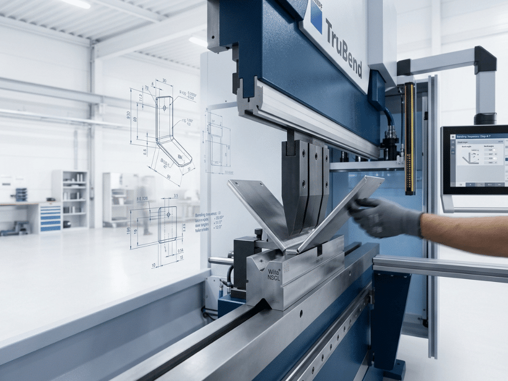
Sheet metal bending is a forming process that plastically deforms a flat metal sheet along a straight axis to create flanges, channels, brackets, and enclosures. A press brake drives a punch into a V-die, forcing the sheet to a set angle without cutting or removing material.
It is the natural choice for low-to-medium volume work when part geometry consists mainly of bends, flanges, and holes. Tooling costs are low, setups change quickly, and iteration from prototype to production is fast. Unlike CNC machining, bending produces no chips and wastes no stock.
It becomes the wrong process when you need very tight flatness over long spans, complex curved surfaces, or volumes high enough that stamping wins on unit cost.
How Material Behavior Controls Your Bend
Most design errors start here. A radius that works in mild steel will crack 6061-T6 aluminum on the first press. Understanding why prevents the kind of failure that only shows up at the fabricator.
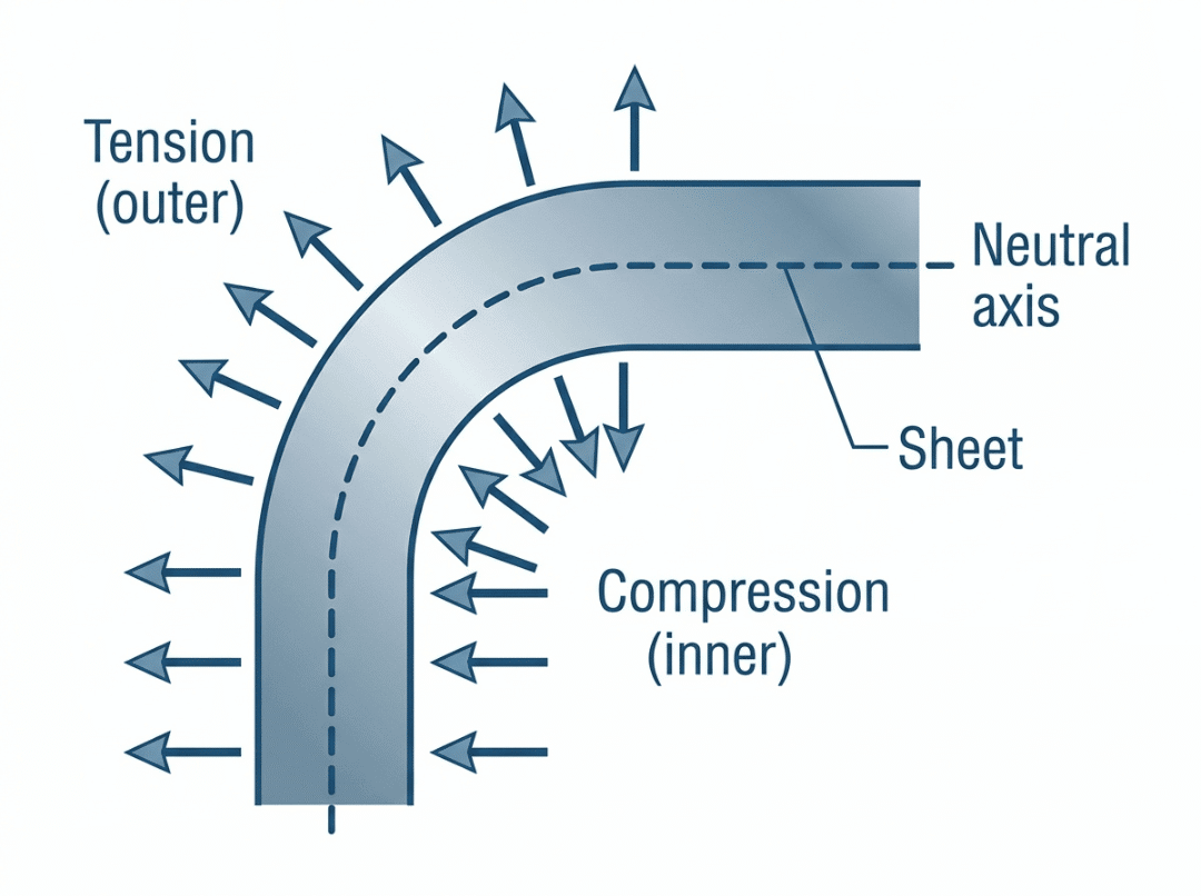
When a sheet bends, the outer surface stretches in tension, and the inner surface compresses. Between them sits the neutral axis—a layer that neither stretches nor compresses. During bending, the neutral axis shifts inward, and the K-factor captures exactly where it lands. Every flat pattern calculation depends on this position.
The Elastic Recovery Problem
All bending starts elastic. The metal resists and wants to return to flat. To hold a permanent angle, the bend must push the material past its yield strength into plastic deformation. Only the plastic portion stays when the press releases. The elastic portion springs back—which is why overbending is always part of production setup, not a sign something went wrong.
High-yield-strength materials such as stainless steel 304 and 6061-T6 aluminum spring back considerably more than mild steel. Shops dial in the correction through test bends. Your drawing’s angular tolerance needs to reflect what the process can actually hold, not what you wish it could.
Work Hardening
As metal deforms plastically in the bend zone, its yield strength increases. This strengthens the finished corner, which is generally useful. The downside is reduced ductility. A work-hardened bend is more vulnerable to cracking under any subsequent forming operation. Stainless 304 work-hardens aggressively, which also explains why its springback is so pronounced.
Grain Direction
Rolled sheet has a grain aligned with the mill’s rolling direction. Bending perpendicular to that grain allows tighter radii and lower crack risk. Bending parallel to it—especially in harder tempers—raises cracking risk considerably.
For 6061-T6 aluminum, grain direction is a production decision, not optional guidance. Orient bend lines perpendicular to the grain where possible, or accept a larger inside radius to compensate.
Minimum Bend Radius: The Most Common Design Mistake
The most frequent error in sheet metal design is specifying a radius that is too tight for the alloy. A “1T minimum” rule appears in many references and is reasonable for mild steel. For several other common materials, it is optimistic enough to cause real failures.
|
Material |
Min Inside Radius |
Springback |
Key Notes |
|---|---|---|---|
|
Mild steel (1018 / A36) |
0.5T–1T |
Low |
Most forgiving; safe starting point |
|
Stainless steel 304 |
1T–1.5T |
High |
Work-hardens fast; plan for overbend |
|
Stainless steel 316 |
1T–1.5T |
Moderate–High |
Similar to 304, slightly less work hardening |
|
Aluminum 5052-H32 |
~1T |
Moderate |
Best all-round aluminum for formed parts |
|
Aluminum 6061-T6 |
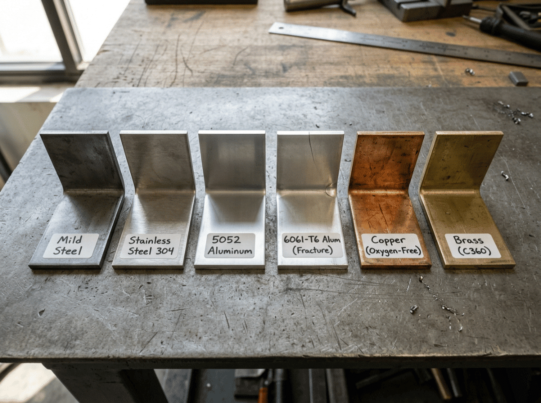
3T–4T minimum |
High |
Cracking below 3T is a predictable failure, not an edge case |
|
Copper C110 (annealed) |
Tight radii achievable |
Low |
Very ductile; few cracking concerns |
|
Brass C260 |
~1T |
Low–Moderate |
Ductile; springs back less than steel |
|
Titanium Grade 2 |
2T–3T+ |
Very high |
Always prove out with test bends first |
On 6061-T6 specifically: The T6 heat treatment delivers excellent structural properties but cuts ductility sharply. Cracking at inside radii below 3T–4T is not a rare edge case—it is a predictable outcome, particularly when the bend runs parallel to the grain. For formed sheet work where formability matters, 5052-H32 is almost always the better choice. If 6061-T6 is required for structural reasons, use a generous radius, verify grain orientation, and confirm tooling with your fabricator before releasing the drawing.
On stainless 304: Its high springback is a property to plan around, not a defect. Air-bent SS304 typically holds ±1° on angle. If your application needs tighter than that, specify bottoming or coining and account for the additional tonnage requirement.
As a consistent rule across all materials: use the largest inside radius your geometry allows. Bigger radii lower tonnage, extend tooling life, and reduce crack risk.
K-Factor, Bend Allowance, and Bend Deduction: Getting the Flat Pattern Right
These three values control how much flat material a bend consumes. A flat pattern built on the wrong K-factor will produce flanges that are consistently off-dimension across every bend on the part. This section explains what each value means and how to apply it.
K-Factor
The K-factor describes where the neutral axis sits within the material thickness during bending:
K = t / T
Where t is the distance from the inside face to the neutral axis, and T is total material thickness.
A K-factor of 0.5 means the neutral axis is centered. In practice it shifts inward, so real values run lower:
- Soft materials (annealed copper, soft aluminum): ~0.35–0.40
- Mid-range (mild steel, 5052 aluminum): ~0.40–0.45
- Hard or high-strength materials: ~0.45–0.50
These are starting values. Shops that work with sheet metal regularly maintain their own K-factor tables derived from test bends on their specific tooling. Those numbers are more reliable than any published reference. Ask your fabricator for their material-specific values before finalizing critical flat patterns.
Bend Allowance
Bend allowance (BA) is the arc length of material at the neutral axis through the bend:
BA = π × (R + K × T) × (A / 180)
Where R = inside radius, K = K-factor, T = thickness, A = bend angle in degrees.
Bend Deduction
Bend deduction (BD) is the amount subtracted from the sum of both outside mold-line dimensions to find the correct flat blank length:
BD = 2 × (R + T) × tan(A / 2) − BA
Both approaches give the same flat length when used correctly. Bend allowance adds to the flat legs; bend deduction subtracts from the outside dimensions. Use whichever your CAD workflow prefers—just be consistent.
Three Worked Examples
Mild Steel, 90° bend
- T = 2 mm, R = 2 mm, A = 90°, K = 0.44
- BA = π × (2 + 0.88) × 0.5 = 4.52 mm
- BD = 2 × 4 × 1 − 4.52 = 3.48 mm
Aluminum 6061-T6, 90° bend with a safe radius
Because 6061-T6 cracks below 3T, the inside radius is set at 6 mm (3T) rather than the mild-steel default.
- T = 2 mm, R = 6 mm, A = 90°, K = 0.42
- BA = π × (6 + 0.84) × 0.5 = 10.74 mm
- BD = 2 × 8 × 1 − 10.74 = 5.26 mm
The larger radius pushes both values up sharply. A mild-steel flat pattern copied into a 6061-T6 design—without recalculating—will produce wrong flange lengths on every bend.
Stainless Steel 304, 90° bend with springback
The flat pattern math is identical to any other material, but the operator’s setup is different.
- T = 1.5 mm, R = 1.5 mm, A = 90°, K = 0.45
- BA = π × (1.5 + 0.675) × 0.5 = 3.42 mm
The flat pattern uses 3.42 mm. Because SS304 at this radius-to-thickness ratio springs back roughly 2°–3°, the operator overbends to approximately 92°–93° so the part relaxes to 90° after release. The flat pattern calculation is correct; the tooling setup absorbs the springback.
If your CAD tool accepts K-factor input—SolidWorks, Fusion 360, CATIA, and Inventor all do—enter a shop-verified value rather than the software default. Always cross-check against fabricator data for critical parts, because a wrong K-factor multiplies error across every bend.
The DFM Rules That Prevent Most Rework
These rules address the problems that appear repeatedly across sheet metal jobs. They are not a complete substitute for a fabricator DFM review, but checking them before submission eliminates the most common rejection reasons.
Minimum Flange Length
A flange too short to grip in the tooling cannot be bent. The standard guideline is 4× material thickness (4T), or 3 mm, whichever is greater. Short flanges are among the most common reasons a drawing gets returned before production. Check every flange before sending files.
Hole-to-Bend Distance
Holes placed too close to a bend line deform into ovals as the metal flows. The rule:
Minimum distance = 2.5 × T + R
For T = 2 mm and R = 2 mm, that is 7 mm from the bend line to the nearest hole edge. Slots and large cutouts need more clearance than round holes. If a hole must sit closer, pierce it after forming, or add bend relief to relieve the stress concentration.
Bend Relief
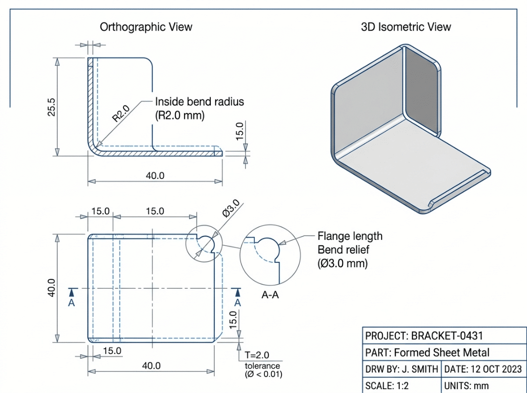
Bend relief is a small rectangular notch cut at each end of a bend line where it meets an adjacent edge or face. Without it, the corner tears or distorts as the material is pulled during forming. Minimum dimensions:
- Width ≥ 1T
- Depth ≥ 1T + inside radius
Add bend relief wherever a bend line terminates at neighboring geometry. It takes seconds in CAD and prevents tearing that cannot be corrected after forming.
Consistent Inside Radius
Using the same inside radius across all bends on a part is one of the more underappreciated cost levers. Every different radius requires a separate die change. If your geometry forces mixed radii, flag it during DFM review—a small design adjustment often eliminates the extra setup entirely.
Achievable Tolerances
For air-bent parts, realistic expectations are:
- Angle: ±0.5°–±1°
- Flat dimensions: ±0.1–±0.25 mm
- Flange length: ±0.25–±0.5 mm
Flag critical dimensions on the drawing and confirm achievability with your fabricator before specifying tolerances that require bottoming or coining.
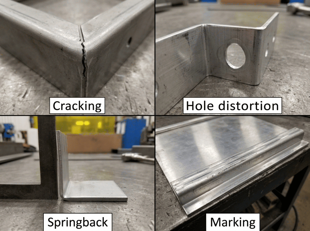
Common Bending Defects: What Causes Them and How to Fix Them
|
Defect |
Most Likely Cause |
Design Fix |
Shop Fix |
|---|---|---|---|
|
Cracking at the bend |
Radius too tight; wrong grain direction; low-ductility temper |
Increase inside radius; orient across grain |
Switch to annealed temper; consider warm forming |
|
Springback / wrong angle |
Insufficient overbend |
Specify realistic angular tolerance |
Adjust overbend; move to bottoming |
|
Hole distortion |
Hole too close to bend line |
Relocate to ≥ 2.5T + R |
Pierce after forming |
|
Bow or warp along flange |
Residual stress; long unsupported flange |
Add stiffening features |
Use backstop; adjust clamping |
|
Surface scratching / marking |
Rough die edge; no protective pad |
Specify larger radius |
Radius die; urethane pad; clean tooling |
|
Short flange failure |
Flange below 4T minimum |
Redesign flange length |
— |
|
Tearing at notch corners |
Missing bend relief |
Add relief ≥ 1T wide × (1T + R) deep |
— |
The pattern here is consistent: design fixes are almost always cheaper than manufacturing workarounds. A missing bend relief caught in CAD takes seconds to add. Torn corners discovered after forming mean scrapped parts.
Press Brake Methods: Choosing the Right One for Your Part
|
Method |
Angle Control |
Tonnage |
Best For |
|---|---|---|---|
|
Air bending |
±0.5°–±1° typical |
Low |
Default process; most versatile |
|
Bottom bending |
Better than air |
Medium |
More consistent angle results |
|
Coining |
Excellent |
Very high |
Tight tolerances, sharp radii |
|
Roll bending |
Radius-defined |
Variable |
Cylinders and arcs |
|
Rotary bending |
Good |
Low–medium |
Coated sheet; reduces marking |
Air bending is the default at most shops. It requires the least tonnage and lets one die set form many angles by adjusting stroke depth. For tolerances tighter than ±1° on angle, bottoming or coining is the realistic path—plan for additional tonnage and tooling accordingly.
Estimating tonnage for air bending in mild steel:
Tonnage ≈ (575 × T² × L) / V
Where T = thickness (inches), L = bend length (inches), V = V-die opening (inches). Multiply by approximately 1.4–1.7 for stainless steel, or 0.5–0.7 for soft aluminum. Treat this as an estimate and confirm with your fabricator.
On bend sequence: For parts with multiple bends, the order of operations determines whether each subsequent bend can reach the tooling. A poorly planned sequence can make certain bends physically inaccessible without re-fixturing. Work through the sequence during design, and confirm it with your fabricator before releasing the job.
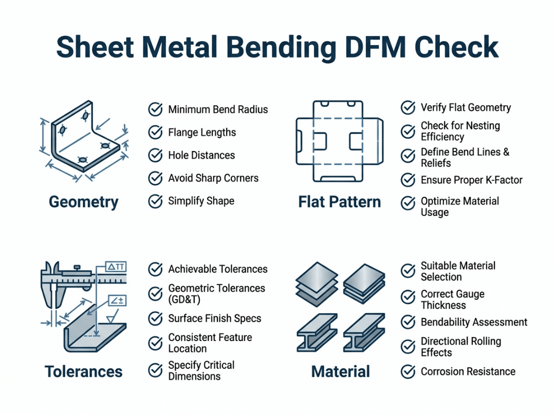
Pre-Release Validation: Ten Checks Before You Send the Drawing
- Confirm material grade and temper.
- Set the inside radius appropriate for that specific alloy.
- Check grain direction against every bend line.
- Verify each flange meets the 4T minimum length requirement.
- Confirm all holes and slots sit at least 2.5T + R from bend lines.
- Add bend relief at every flange termination adjacent to neighboring geometry.
- Review the bend sequence for tool access on multi-bend parts.
- Enter a shop-verified K-factor in your CAD tool—not the software default.
- Compare the generated flat pattern against fabricator data.
- Request a first-article DFM review before production begins.
DFM Checklist
Geometry
- Inside radius ≥ 1T for mild steel; ≥ 3T–4T for 6061-T6
- All flanges ≥ 4T or ≥ 3 mm, whichever is greater
- All holes and slots ≥ 2.5T + R from every bend line
- Bend relief added at all flange terminations
- Consistent inside radius used across the part where possible
- Bend sequence reviewed for tool accessibility
Flat Pattern
- K-factor confirmed with fabricator for material and tooling
- Bend allowance verified by calculation or test bend
- Flat pattern checked for interference between bends
Tolerances
- Angular tolerances ≥ ±0.5° for air bending, or bottoming/coining specified where tighter
- Critical dimensions identified and confirmed with fabricator before release
Material
- Grain direction reviewed for crack-sensitive alloys
- Temper confirmed appropriate for the required radius
- Springback compensation approach discussed with the shop
Drawing Completeness
- Material grade, thickness, and surface finish specified
- Bend angle and inside radius called out on every bend
- DFM review requested for first article or new geometry
Frequently Asked Questions
What is the minimum bend radius for sheet metal?
For mild steel, 1T is a reliable starting minimum. Stainless steel typically requires 1T–1.5T. Aluminum 6061-T6 often needs 3T–4T or more due to reduced ductility from heat treatment. Confirm with your fabricator based on your specific alloy and temper.
What is K-factor and why does it affect flat pattern accuracy?
K-factor is the ratio of the neutral axis position to total material thickness. It determines how much material a bend consumes. A wrong K-factor shifts every flange length and overall dimension across the entire part. Use shop-confirmed values rather than textbook defaults.
What is the difference between bend allowance and bend deduction?
Bend allowance is the arc length at the neutral axis, added to the flat leg dimensions to find total blank length. Bend deduction is subtracted from the sum of the two outside mold-line dimensions to reach the same result. Both approaches, applied correctly, give the same flat blank length.
What causes springback, and how is it handled?
Springback is elastic recovery after the press brake releases pressure. High-yield-strength materials recover more than low-strength ones. Shops correct for it by overbending—pressing past the target angle so the part relaxes to the correct angle after release. Bottoming and coining reduce springback by more fully plasticizing the bend zone.
How far should holes be from a sheet metal bend?
At least 2.5T + R from the bend line to the nearest hole edge. For T = 2 mm and R = 2 mm, that is 7 mm minimum. Holes placed closer than this distort during forming.
Is 6061-T6 aluminum a good choice for sheet metal bending?
It can be bent, but it requires deliberate design choices. The T6 temper cuts ductility, making cracking at inside radii below 3T–4T a predictable outcome rather than an occasional problem, particularly when bending parallel to the grain. For most formed sheet applications, 5052-H32 is the more practical choice. If 6061-T6 is required for structural reasons, use generous radii, orient bends across the grain, and confirm tooling before releasing to production.
What angular tolerances can press brake bending achieve?
Air bending typically holds ±0.5°–±1° on angle and ±0.1–±0.5 mm on linear dimensions, depending on material and geometry. Tighter requirements need bottoming or coining, with the associated increase in tonnage.
What is bend relief, and when is it required?
Bend relief is a small rectangular notch at the ends of a bend line where it meets an adjacent edge. Without it, the corner tears during bending. Size it at ≥ 1T wide and ≥ 1T + inside radius deep. Add it any time a bend line terminates at neighboring geometry.
Get a DFM Review Before Production Starts
Most bending problems are straightforward to correct at the design stage and expensive to deal with after parts are made. Catching a missing bend relief, a flange that is 1 mm too short, or a radius that will crack 6061-T6 before the job reaches the press brake saves time, material, and rework cost.
Essengold’s engineering team reviews sheet metal drawings for DFM compliance as part of the quoting process—checking bend radius, hole clearances, flange length, bend relief, and flat pattern accuracy before production begins. If you are also sourcing custom metal fabrication or need machined components alongside bent parts, both can be reviewed together.