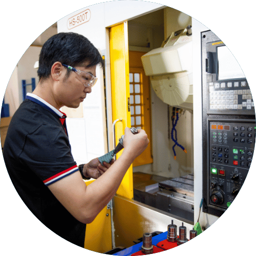
Computer-aided design (CAD) is the use of software to create, edit, analyze, and document precise 2D drawings and 3D models of physical products, parts, and structures. It replaced the pencil, T-square, and drafting board with exact digital geometry that can be revised quickly, shared easily, and carried forward into prototyping, manufacturing, and technical documentation.
The real value of CAD shows up when a design changes. Imagine an engineer finishing a motor mount when the fastener size shifts from M6 to M8. She updates the hole feature once, and the model rebuilds in seconds. The drawing updates automatically, and the mating plate in the assembly immediately reveals that its hole pattern no longer aligns. On paper, the same revision would have meant redrawing multiple views by hand and manually checking that nothing was missed. That difference is why CAD matters. It does more than help people draw. It helps teams control change, catch problems earlier, and move from concept to production with less guesswork. This guide explains how CAD works, the main types of CAD, where it is used, and where its advantages — and limitations — are most visible.
What Is Computer-Aided Design (CAD)?
Computer-aided design (CAD) is the use of software to create, refine, and document precise digital representations of physical parts, products, and structures. What makes CAD different from illustration software or 3D art tools is that its geometry carries real, measurable values. A circle in a CAD program is not just a picture of a circle. It is a mathematically defined curve with a precise center point and radius that can be queried, constrained, and edited. That is what allows CAD models to support technical drawings, assemblies, simulation, and manufacturing workflows instead of serving as visual artwork alone.
In practice, CAD usually produces four main outputs: 2D technical drawings, 3D part models, multi-part assemblies, and exchange files that other teams, suppliers, and machines can use downstream. The basic idea dates back decades, to Ivan Sutherland’s Sketchpad in 1963, which showed that computers could do more than display drawings—they could help define and manipulate geometry interactively.
CAD is where an idea first becomes precise enough to test, quote, revise, and build. That is why so much depends on it downstream, from prototypes and supplier quotes to tooling plans and final inspection. It also connects to two closely related toolsets: CAE (computer-aided engineering), which evaluates how a design performs, and CAM (computer-aided manufacturing), which turns finished geometry into machining instructions. The real advantage of CAD is not simply that it makes drawing faster. It lets teams answer expensive questions while changes are still cheap. A well-built model can reveal whether parts will fit, whether a bracket can carry its load, and whether a machine shop can realistically produce the part at the tolerances specified — all before any material is cut.
Core Building Blocks of a CAD Model
Almost every 3D model — from a simple washer to a full gearbox — is built from the same five elements:
- Sketches: 2D profiles drawn on a flat plane that serve as the starting point for 3D features. If the sketch is weak or poorly organized, the rest of the model usually inherits those problems.
- Constraints and dimensions: Rules that lock geometry into place, such as parallel lines, concentric holes, or a fixed 50 mm edge length. A fully constrained sketch is far more stable when the design changes later.
- Features: The operations that turn sketches into 3D form. Extrude adds depth, revolve sweeps a profile around an axis, and fillet rounds an edge. Other common features, such as holes, shells, and chamfers, follow the same logic.
- Feature tree (history): The ordered record of how the model was built. Because the software stores that sequence, a designer can return to an earlier step, make a change, and let later features rebuild automatically.
- Assemblies: Multiple parts positioned together using mates or relationships, such as one face sitting flush against another or a shaft rotating inside a bore. Assemblies show how components fit, move, and function as a system.
How Does CAD Work?
CAD is not a single act of drawing. It is a workflow that turns design intent into geometry, checks that geometry against real-world constraints, and then converts it into files other people can build from. Most CAD projects follow the same basic path, even when the part itself is different. To make that path concrete, consider a simple example: an aluminum camera bracket that bolts to a robot arm.
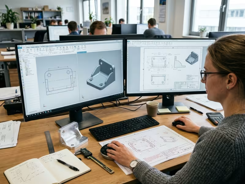
Define requirements. Before any modeling starts, the designer needs to know what the part has to do. In this case, the bracket must support a 0.8 kg camera, match a 60 mm hole pattern on the arm, clear an existing cable harness, and be machinable from 6061 aluminum. Those requirements are not background details. They become the constraints that drive every modeling decision that follows.
Sketch and constrain. The designer begins with a 2D sketch of the bracket’s L-shaped profile and adds dimensions for height, length, and wall thickness. Then the sketch is constrained until its geometry is fully defined. This step matters more than many beginners realize. If the sketch is underconstrained, the model may rebuild unpredictably later, with edges shifting or features moving in ways the designer did not intend.
Build 3D features. Once the sketch is stable, it becomes a solid part. The profile is extruded to width, mounting holes are added using a hole feature that stores thread or clearance information, and fillets are applied to internal corners. A lightening pocket may be cut to remove unnecessary mass. What began as a flat profile is now a body with volume, weight, and measurable surface area.
Assemble and check. The bracket is then placed into an assembly with the robot arm and the camera. At this stage, CAD starts proving its value. An interference check can show that one bolt head collides with the cable guide. The designer shifts the hole pattern 4 mm, rebuilds the assembly, and resolves the issue before any stock is cut or any prototype is ordered.
Validate. With the geometry in place, the software can report mass properties such as weight and center of gravity. A quick stress check may also estimate how much the bracket deflects under load. That kind of first-pass validation is often enough to catch obvious weaknesses early. If the part is highly loaded, safety-critical, or sensitive to heat or vibration, the work usually moves into dedicated CAE tools for deeper analysis.
Document and export. The final step is turning the model into something others can use. A 2D drawing is generated from the part, complete with views, dimensions, tolerances, and thread callouts. The 3D model is exported as a STEP file for manufacturing or supplier review. For machined parts, a STEP file plus a dimensioned PDF drawing is the standard handoff package: the model provides exact geometry, while the drawing clarifies which tolerances, finishes, and notes matter.
That workflow holds across almost every CAD project. Requirements become geometry, geometry is checked against fit and function, and verified geometry becomes documentation. In that sense, CAD is not just a drafting tool. It is a system for controlling change and reducing ambiguity before production begins.
What Happens Under the Hood: Geometry Kernels and File Formats
Behind the interface, every CAD program runs on a geometry kernel — the mathematical engine that stores and calculates shapes. Most CAD kernels represent solids using boundary representation, or B-rep, where a part is defined by the faces, edges, and vertices that enclose it. Curved surfaces are often represented with NURBS, a class of mathematical curves that can describe everything from a simple cylinder to a complex freeform housing with high precision. That is one of the key reasons CAD geometry is dimensionally exact. It is not an image, and it is not just a mesh of visual polygons. It is a mathematical description of shape.
File formats become important as soon as a design leaves the original CAD system. Native files preserve the full feature history, but they are often tied to the software that created them. Neutral formats are built for exchange. STEP is the standard format for sharing 3D solid geometry between systems. IGES is older and still appears in surface-heavy or legacy workflows. STL converts a model into triangles for 3D printing, which is useful for printing but loses the exact curves and parametric intelligence of the original model. DWG and DXF are common for 2D drawings and flat cutting profiles. The practical rule is simple: share the format that preserves the information the next team actually needs. For most machined parts, that means a STEP file for geometry and a dimensioned PDF drawing for tolerances, finishes, and manufacturing notes.
What Are the Main Types of CAD?
There is no single way to classify CAD. In practice, people usually describe it in three different ways: by dimension, by how 3D geometry is represented, and by how models are built and edited. Those distinctions matter because they affect not only what you can design, but also how easy the design is to revise, validate, and hand off downstream.
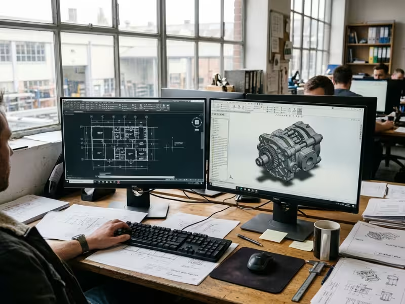
2D CAD
2D CAD produces flat drawings built from lines, arcs, text, dimensions, and layers. It is the direct digital successor to the drafting board. There is no true depth, volume, or mass in the model itself. Instead, shape is communicated through views, sections, notes, and dimensions that the reader has to interpret correctly.
That simplicity is still a real advantage in the right context. 2D CAD remains the standard for floor plans, electrical schematics, P&ID diagrams, sheet-metal flat patterns, and profiles prepared for laser or waterjet cutting. When the deliverable is a layout or a cut path rather than a full 3D object, 2D is often faster to create, lighter to share, and easier to mark up. Even teams that do most of their design work in 3D still rely on 2D drawings for manufacturing release, approvals, and compliance documentation.
3D CAD: Wireframe, Surface, and Solid Modeling
3D CAD adds depth, but not all 3D models carry the same kind of information. The three main modeling approaches are wireframe, surface, and solid modeling.
- Wireframe modeling: Represents an object using only points, lines, and curves. It does not define faces or enclosed volume, which means the same wireframe can often be interpreted as more than one shape. Today it is used mainly for concept layouts, reference geometry, and certain legacy workflows.
- Surface modeling: Describes the outer skin of a shape without defining its interior volume. It is especially useful when curvature quality matters more than internal mass, as in automotive body panels, aircraft fairings, and consumer product housings with complex organic forms.
- Solid modeling: Defines a fully enclosed volume with a clear inside and outside. Because the software knows exactly where material exists, solid modeling is the standard for mechanical parts, assemblies, and anything that will move into machining, molding, or inspection.
In practice, these methods are often combined. A designer may build the outer form of a handheld product as a surface model, then convert or thicken that skin into a solid so it can be engineered for tooling and production.
Parametric vs. Direct Modeling
Another important distinction is how a model is built and changed. Parametric modeling is driven by dimensions, constraints, and feature history. If you change a key value — for example, increasing a plate thickness from 6 mm to 8 mm — the related holes, pockets, and fillets update automatically while preserving the logic of the design. That makes parametric modeling especially useful for configurable products, part families, and any design where revisions are expected to follow clear rules.
Direct modeling works differently. Instead of relying on a stored history, it lets the designer select geometry and modify it directly by pushing, pulling, offsetting, or rotating faces. That makes it faster for early concept work, quick one-off changes, and editing imported STEP files that arrive with no usable feature tree. If a supplier sends over a model and one face needs to move 3 mm, direct modeling may solve the problem in seconds. Rebuilding the same change parametrically from scratch could take far longer. In professional workflows, the choice is rarely absolute. Most modern CAD systems support both approaches, and experienced users switch between them depending on whether structure or speed matters more.
2D vs. 3D CAD at a Glance
For many teams, the most practical choice is not between software brands but between a 2D and 3D workflow. The difference is usually straightforward:
| Criteria | 2D CAD | 3D CAD |
|---|---|---|
| Output | Flat drawings, layouts, cut profiles | Solid or surface models, assemblies, drawings |
| Visualization | Shape is interpreted from views | Model can be rotated, sectioned, and rendered |
| Error detection | Mostly manual review | Interference and clearance checks can be automated |
| Learning curve | Shorter | Longer, especially in parametric workflows |
| Typical uses | Floor plans, schematics, sheet-metal flats | Mechanical parts, products, complex assemblies |
Key Features of CAD Software
What makes CAD valuable in practice is not just that it can create geometry. It is that the geometry can be edited, checked, documented, reused, and shared without losing control of the design. The most useful CAD features are the ones that reduce rework, expose mistakes earlier, and keep the model aligned with everything downstream.
-
Precision geometry and dimensioning: Every line, arc, hole, and surface is defined by an exact numerical value. A hole placed at 25.000 mm is not approximately there — it is exactly there, and that same number carries through to drawings, inspection, and manufacturing outputs. This level of precision is one of the main reasons CAD works in engineering and production environments.
-
Parametric editing and design tables: A single change can propagate through the entire model without forcing the designer to rebuild it from scratch. Design tables extend that logic even further by driving multiple variants from one master model, such as a bracket offered in five different lengths or mounting patterns. This is especially useful when products share the same core geometry but differ in size or configuration.
-
Assembly modeling and interference detection: CAD does not stop at individual parts. It also shows how those parts fit together. Assembly tools can detect collisions, insufficient clearances, and motion conflicts long before a prototype is built. In many cases, this is where CAD delivers some of its biggest savings, because fit problems are far cheaper to fix on screen than on the shop floor.
-
Automatic drawing generation: 2D drawings, section views, and dimensions are generated directly from the 3D model and stay linked to it. When the model changes, the drawing updates as well. That connection matters because one of the most common sources of production error is a drawing that no longer matches the latest design revision.
-
Standard component libraries: Fasteners, bearings, structural sections, and other common elements can be inserted from prebuilt libraries instead of recreated each time. This saves design time, but it also improves consistency. Reusing validated standard components is usually faster and less error-prone than modeling them repeatedly from scratch.
-
Collaboration and version control: Modern CAD workflows often include cloud sharing, comments, markup, and revision tracking so that engineers, designers, suppliers, and reviewers can work from the same current dataset. That reduces the version confusion that often comes from passing files around by email and makes design reviews far more reliable.
What Is CAD Used For? Applications Across Industries
CAD appears anywhere physical objects, structures, or systems have to be defined precisely before they are built. What changes from one industry to another is not the basic purpose of CAD, but the type of geometry that matters most, the form of the final deliverable, and how tightly the model connects to manufacturing, construction, or inspection downstream.

Mechanical engineering and manufacturing. In mechanical work, CAD is used to create parts, fixtures, jigs, tooling components, and full machine assemblies. Solid, parametric modeling is the norm because dimensions, tolerances, and fit relationships have to hold through revision after revision. The CAD model often becomes the foundation for CNC machining, inspection planning, and supplier communication, which means a mistake in the model rarely stays confined to the design department.
Architecture and construction. Architects and building teams use CAD for floor plans, elevations, sections, and increasingly for full building models. Traditional 2D drafting still plays a major role in construction documents because contractors and inspectors often work from drawings, not just models. BIM extends that logic by attaching data such as materials, quantities, schedules, and costs to the geometry itself, turning the model into both a design tool and a coordination tool.
Automotive. Automotive design relies heavily on both surface and solid modeling. Surface tools are essential where curvature quality, reflections, and exterior form matter, such as body panels and interior trim. Solid modeling is used for brackets, housings, mounts, and mechanical systems where the concern is not just shape but packaging, fit, and production feasibility. Large assemblies let teams check clearances and conflicts virtually before committing to expensive tooling.
Product and industrial design. Consumer products such as electronics, appliances, tools, and wearables often sit at the intersection of appearance, ergonomics, and manufacturability. CAD supports that balance by letting teams move from concept models to prototype-ready geometry without losing control of dimensions or part interfaces. Surface and solid workflows are often combined, especially when a product needs both refined outer form and production-ready internal structure.
Aerospace. Aerospace programs depend on CAD because they involve complex assemblies, strict revision control, and heavy documentation requirements. A single system may include thousands or tens of thousands of components, all of which have to fit, function, and trace back to approved design data. In that environment, CAD is not just a modeling tool. It is part of the configuration-control system that keeps highly regulated engineering work coherent.
Electronics. In electronics development, ECAD handles the circuit board while MCAD handles the enclosure, mounting features, heat sinks, and connector interfaces around it. The two have to exchange data accurately, because a board that works electrically is still a failed design if it cannot fit its housing, clear its fasteners, or align with external ports. CAD matters here because it helps close the gap between electrical intent and physical reality.
Advantages of CAD
CAD delivers its biggest advantages where manual drafting and disconnected workflows used to create ambiguity, delay, or rework.
-
Accuracy: In CAD, geometry is defined by numbers rather than by line quality, print scale, or the drafter’s hand. That sharply reduces the kinds of errors that used to creep into drawings through misread dimensions, scaling mistakes, or manual redrafting.
-
Faster iteration: A parametric revision can update a model in minutes instead of forcing a full redraw. That speed matters not only because it saves time, but because it makes teams more willing to explore alternatives. In practice, CAD often leads to better designs, not just faster documentation.
-
Errors caught early: Interference checks, clearance analysis, and assembly review expose problems before prototypes are built or tooling is ordered. Moving a hole or adjusting a wall thickness on screen is routine. Finding the same mistake after a mold is cut or a machined batch is completed is expensive.
-
Clearer communication: 3D models, section views, and derived drawings make design intent easier to understand across teams. That matters when reviewers include sourcing teams, managers, suppliers, or customers who may not read technical drawings fluently but still need to understand what is being built.
-
Direct manufacturing handoff: The same model can feed machining, 3D printing, inspection, and other downstream processes. That removes the need for someone else to recreate the geometry from a drawing, which is one of the most common sources of avoidable interpretation errors.
-
Reuse and standardization: Libraries, templates, and configurable model families allow teams to build on validated geometry instead of starting from scratch every time. In many real-world product lines, the next design is not entirely new. It is a controlled variation of something the team already knows how to make.
Limitations of CAD
For all its strengths, CAD also brings risks and constraints that are easy to underestimate.
-
Learning curve: CAD is not only difficult to learn well; it is easy to learn badly. A model may look acceptable on screen while still being fragile under revision because the sketch is underconstrained, the feature order is unstable, or the design intent was never captured properly. Training helps, but modeling standards and review discipline matter just as much.
-
Software and hardware cost: Professional CAD is not just a software expense. It often includes simulation modules, data-management tools, and workstations capable of handling large assemblies or complex surfaces. The cost issue is not simply whether CAD is expensive, but whether the chosen system matches the actual workload well enough to justify its overhead.
-
File compatibility: Moving files between CAD platforms can strip away feature history, alter surfaces, or create subtle geometry problems that are not obvious until later. Neutral formats such as STEP reduce the risk, but they do not preserve everything. Translated files still need to be checked before they are trusted.
-
False confidence: A CAD model can be dimensionally complete, visually clean, and still difficult or impossible to manufacture efficiently. Sharp internal corners, inaccessible pockets, unrealistic tolerances, and weak tooling assumptions do not always reveal themselves in the model alone. That is why design-for-manufacturing review remains essential before release to production: it catches the issues the geometry itself cannot fully explain.
CAD vs. Manual Drafting
CAD did more than make drafting faster. It changed what a design document is. In manual drafting, the drawing is a static record that has to be revised, copied, and checked by hand. In CAD, the drawing is usually tied to an underlying digital model, which means geometry, views, dimensions, and revisions can stay connected instead of being managed as separate pieces of information.
| Criteria | Manual Drafting | CAD |
|---|---|---|
| Precision | Limited by scale, instruments, and the drafter’s hand | Numerically exact |
| Revision speed | Erase and redraw every affected view | Edit once; linked views update |
| Storage and sharing | Physical sheets, blueprints, and archives | Digital files, shared instantly |
| 3D capability | Projected views only | True 3D models and assemblies |
| Reuse | Redraw, trace, or manually adapt | Copy, configure, and use standard libraries |
That does not mean sketching has disappeared. For early concept exploration, a rough hand sketch is still one of the fastest ways to work through an idea, test proportions, or discuss options before committing them to constrained geometry. What CAD replaces is not quick thinking on paper, but the need to carry formal design definition through manual drafting.
CAD vs. CAM vs. CAE: How They Fit Together
These three acronyms are often treated as the same thing, but they serve different roles in the product development workflow.
| Tool | Main Job | Typical Output |
|---|---|---|
| CAD (computer-aided design) | Defines geometry and captures design intent | 3D models, assemblies, technical drawings |
| CAE (computer-aided engineering) | Evaluates how the design will perform | Stress, thermal, vibration, and flow results |
| CAM (computer-aided manufacturing) | Plans how the part will be made | Toolpaths and G-code for machine tools |
The easiest way to understand their relationship is to follow a single design through the process. A designer builds the camera bracket in CAD. CAE then runs a stress simulation and shows that the inside corner of the L-bend is carrying too much load. The designer returns to CAD, increases the wall thickness from 4 mm to 5 mm, and enlarges the fillet radius. Once the revised geometry passes review, the model can move into CAM, where machining toolpaths are generated for production.
The important point is that CAD remains the source model throughout. CAE and CAM both depend on the geometry defined in CAD, but they use it for different purposes: CAE asks whether the design will perform, while CAM asks how the approved design will actually be made. They are connected systems, but they are not interchangeable.
Conclusion
CAD is where an idea becomes a precise, manufacturable, and communicable definition of a physical thing. The quality of that model determines how accurately everything downstream — quotes, simulations, toolpaths, inspection — reflects the designer’s actual intent.
Match the tool to the job: 2D for layouts and cut profiles, 3D for parts and assemblies. Build with clean constraints so models survive revisions. When you’re ready to take a design into production, send a STEP file paired with a dimensioned PDF drawing. That combination gives a machining partner like Essengold everything needed to quote accurately, raise manufacturability concerns early, and produce parts that match the model the first time.