A prototype has one job: to tell you the truth about your design before you spend real money on tooling. But not every prototype tells the truth. A part that looks right can still lie about how it will behave under load, at temperature, or after a thousand cycles — and by the time you find out, the design is frozen and the mold is cut.
That gap is why CNC prototype machining matters. If you’re a product designer, mechanical engineer, or working in medical, aerospace, or automotive R&D, you need parts that behave like the real thing — not approximations that pass a quick fit check and fail everywhere else. CNC gives you functional parts in production materials, often in a few days, with no mold cost and no tooling commitment.
Read on, and you’ll know when CNC is the right call, how to design a part that machines cleanly the first time, and how to read a quote well enough to control both cost and timeline.
What CNC Prototype Machining Gets You
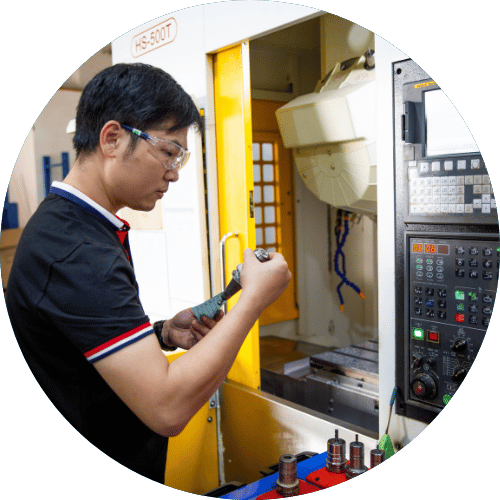
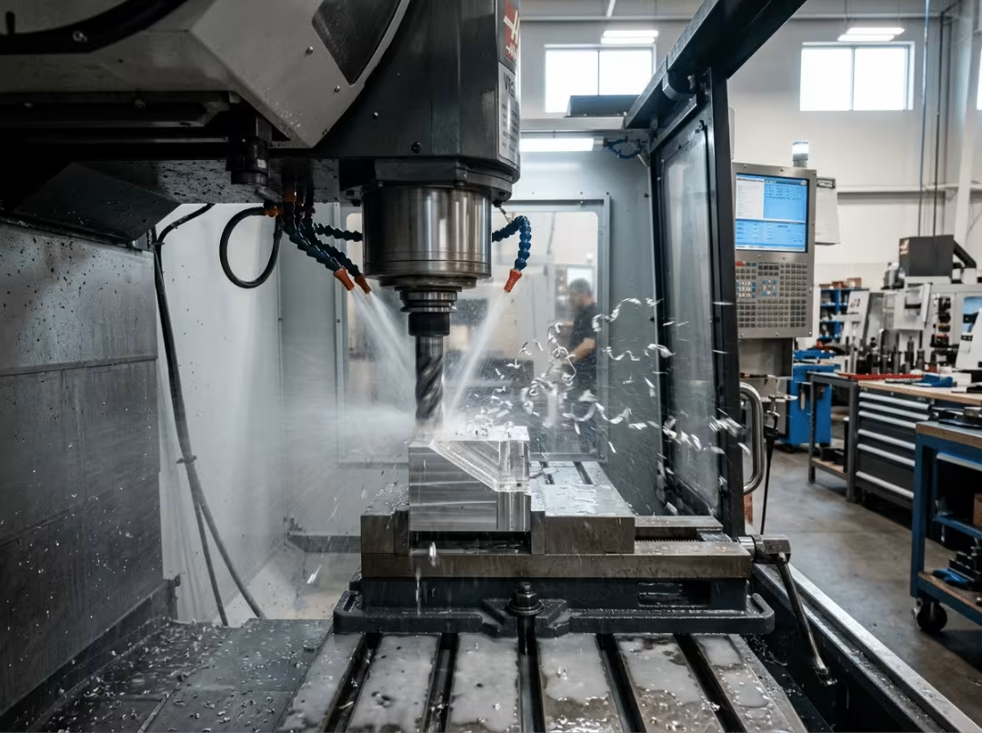
CNC prototype machining uses computer-controlled cutting tools to remove material from a solid block until a finished part is produced. That’s the mechanics — but it’s not the point.
The point is this: a CNC prototype runs on the same machines and the same materials as your production parts. Cut a bracket from 6061 aluminum on a prototype, and it’s the same 6061 you’ll run at volume. Your test data carries over. When the part passes a load test, a thermal cycle, or a fit-and-function review, you’re seeing how the production part will behave — not a plastic stand-in that merely shares the shape. That fidelity is the whole reason to reach for CNC over faster, cheaper form-study methods.
When CNC Is the Right Choice — and When It Isn’t
CNC isn’t always the answer. Knowing when to use it and when to skip it saves you both money and wasted iterations.
Choose CNC when:
- Material behavior is what you’re testing. You need real mechanical, thermal, or wear performance — not just a shape you can hold.
- Accuracy matters. You want ±0.005 inches as a baseline, with tighter control available where the function demands it.
- The design is still moving. You’ll iterate between versions, and paying for tooling would lock you in too early.
- You need production-matching finishes. Anodizing, bead blasting, and similar finishes make customer-facing samples look like the real product.
Reconsider CNC when:
- Quantities are very low, and the geometry is simple. Programming and setup dominate the price on one-offs, so the cost per part stays high.
- The geometry hides from the cutter. Internal lattices, deep narrow channels, and enclosed voids are hard or impossible to machine — additive may be the better route.
- The part won’t fit the machine. Every mill and lathe has a work envelope, and oversized parts force splits or a different process.
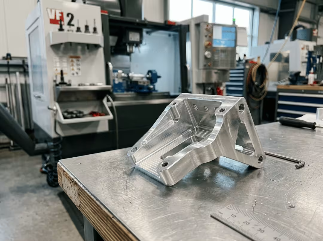
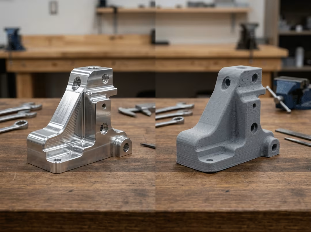
Here’s the decision in one scenario. You’ve designed a structural bracket that must pass a load test. Machine it from 6061 and you get a part that fails — or holds — exactly the way the production part will. Print the same bracket, and it might pass a fit check on your desk while giving you numbers that badly mislead you about strength. When the answer you need is “will this actually hold,” CNC is the only prototype that answers honestly.
Designing a Part That Machines Right the First Time
This is where most prototype budgets get won or lost. A clean design quotes fast and cheap. A careless one collects setups, specialty tooling, and revision loops — and you pay for every one of them.
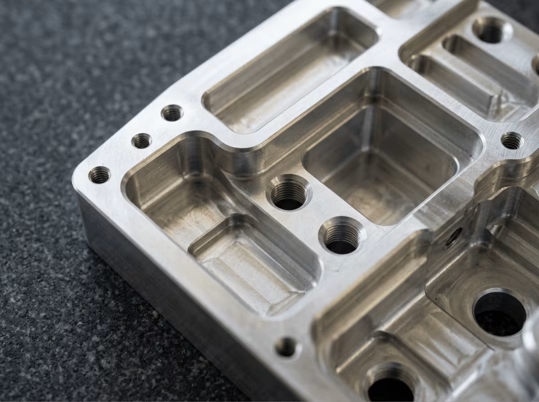
Geometry rules that save real money. Internal corners are the classic trap. A cutting tool is round, so it can’t produce a sharp internal corner. Design your internal radii to match a standard tool radius, and the shop cuts them in a single pass. Demand a true sharp corner, and you’ve just forced EDM or slow specialty work onto a part that didn’t need it. Keep walls thick enough to resist deflection — thin walls chatter under the cutter, wreck the finish, and sometimes get scrapped mid-run. And favor standard hole sizes and thread depths, because off-standard holes mean custom tooling and longer lead times.
Features that quietly add cost. Some choices look harmless on screen and blow up the quote. Deep holes need long, slender tools run at slow feeds, so they eat machine time. Undercuts can’t be reached by a standard cutter at all — they force specialty tooling or a separate EDM operation. Tall ribs and thin walls vibrate during cutting, which hurts surface finish and can push parts out of tolerance. None of these are dealbreakers, but each one has a price, and the price is often invisible until the quote lands.
The drawing that gets you an accurate quote. A vague drawing gets you a padded quote or a revision loop — both cost days. Call out only the tolerances that actually matter, and mark which dimensions are critical so the shop knows where to focus inspection. Specify the material grade explicitly, along with any required certifications. And send a complete drawing the first time. Every round of “wait, what did you mean here?” adds days to a schedule you’re trying to compress.
Consider what one geometry decision can do. A part designed with a corner radius matched to a standard end mill, and a feature relocated so the tool can reach it from above, might machine entirely in a 3-axis setup. Force a tight internal corner or bury a feature where only an angled approach reaches it, and the same part jumps to a 5-axis machine — higher hourly rate, more setup, longer lead time. The geometry didn’t get more useful. It just got more expensive. Understanding design-for-manufacturability principles before you finalize the model is the single most reliable way to avoid that outcome.
Tolerances and Finishes — Spend Where It Counts
Tolerances and finishes are where engineers quietly overspend, usually out of caution. The fix isn’t to loosen everything — it’s to put precision where the function needs it and nowhere else.
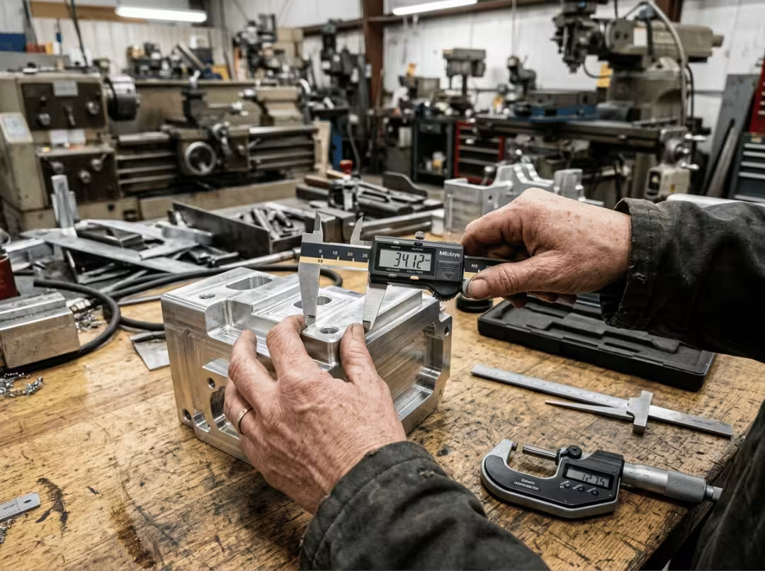
How tight is tight enough. Most shops hold ±0.005 inches as a standard tolerance, and it costs you nothing extra. Push to ±0.001 inches, and the picture changes: slower machining, more careful setups, and added inspection all factor into your quote. Tight tolerances earn their keep on a bearing fit or a mating surface. They’re pure waste on a face that never touches anything. Every feature you constrain adds cost, so tolerance the function, not the whole part.
Match the finish to the part’s purpose. A functional test part usually works fine as-machined — visible tool marks don’t affect a load test. A customer-facing sample is different; bead blasting, anodizing, or powder coating make it look like the finished product. The CNC machining surface finish guide covers the full range of available options, from SPI grades to common post-processing treatments, and is worth a look before you finalize your finish callout. Before you commit, also ask the shop which finishes they run in-house and which they outsource, because anything sent out adds lead time you may not have budgeted.
The most common way to inflate a quote is invisible: a tight tolerance called out on an internal feature nobody will ever measure. It doesn’t touch a mating part, it doesn’t carry load, and no inspector will check it — but the shop still has to machine and verify to that spec, and you still pay for it. Before you finalize a drawing, walk every tight callout and ask one question: does the function actually need this? If it doesn’t, loosen it and keep the money.
Cost and Lead Time — How to Read a Quote
The number on a prototype quote isn’t one price — it’s a stack of them, and knowing what sits in the stack tells you where you can actually save.
On a one-off part, the surprise is that cutting is rarely the biggest line. Programming the tool paths and setting up the machine often cost more than the metal removal itself. Someone has to write the CAM program, pick the tools, dial in speeds and feeds, then fixture the block and probe it before a single chip flies. That work is the same whether you order one part or ten — which is exactly why quantity changes everything. A batch of 10 spreads that fixed setup across every part, so the per-part price drops sharply as the count climbs.
After setup, the drivers are predictable. Material grade and stock size feed straight into the quote. Tight tolerances add machine time and inspection. Complex geometry adds setups, and every extra setup is another fixturing and alignment cycle you pay for.
Timelines follow the same logic. A simple aluminum part machined in one setup can ship in 2 to 3 business days. Add multiple setups, or switch to stainless, which cuts slower and wears tools faster, and you’re looking at 5 to 10 days. Rush service compresses that schedule, but you pay a premium for jumping the queue.
To cut the bill without cutting corners:
- Simplify the geometry so it can be machined in fewer setups.
- Stick to common materials and standard stock sizes — custom blocks add waste and cost.
- Batch your design iterations into a single order instead of paying setup fees twice.
- Send a complete drawing the first time so no revision loop eats your schedule.
The pattern holds throughout: fixed costs reward volume and clean drawings, and variable costs reward restraint on tolerance and geometry.
How Material Choice Changes the Outcome
The principle comes first: the harder or more exotic the material, the slower it cuts, the faster it wears tools, and the longer you wait for stock. That single fact drives cost and lead time more than most design details.
A few groupings cover most prototype work:
- Aluminum (6061, 7075): the default. Fast to cut, strong, light, and cheap — start here unless the application rules it out.
- Stainless (303, 304): corrosion resistance and medical-grade cleanliness, at the cost of slower machining and shorter tool life.
- Titanium: the best strength-to-weight you can get, but it cuts slowly, burns through tooling, and carries a steep material price.
- Plastics (ABS, PC, Delrin, PEEK): enclosures and impact parts in ABS or polycarbonate, low-friction precision in Delrin, high-temperature and sterilizable needs in PEEK — with PEEK the most expensive by a wide margin.
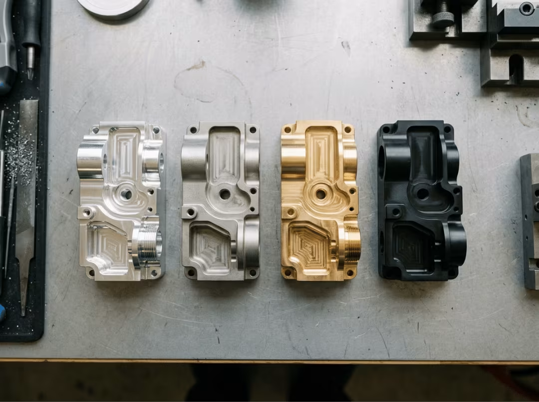
One habit saves real money: design around standard block sizes. Stock the shop already has on the shelf trims both waste and lead time. Custom sizing means extra material, extra scrap, and a wait for delivery before machining even starts.
CNC vs. Other Methods — Which Should You Use
CNC isn’t the only way to make a prototype, and choosing the wrong process wastes both money and time. The choice comes down to what you’re testing and how many parts you need.
CNC vs. 3D printing. CNC cuts from production materials, so the part behaves like the real thing under load, heat, and wear. 3D printing wins where geometry beats material — internal channels, lattices, and organic shapes a cutter can’t reach — and it’s unbeatable for a fast form study you just need to hold. As a rule, testing performance means CNC; checking shape quickly means print.
CNC vs. vacuum casting. Vacuum casting uses a silicone mold to pour 10 to 50 polyurethane parts, and it shines when you need a small batch of rubber-like or cosmetically finished copies. CNC beats it on single parts and on material range, since casting is limited to castable resins.
CNC vs. injection molding. Injection molding only earns its keep at volume — the tooling is expensive and slow to build, and design changes get costly once steel is cut. For one to a few dozen parts, or whenever the design is still moving, CNC is faster and cheaper.
Map it to your situation:
- 1–20 functional parts, real material behavior: CNC.
- 1 quick shape check, complex internal geometry: 3D printing.
- 10–50 cosmetic or flexible parts: vacuum casting.
- Thousands of identical parts, design locked: injection molding.
How to Choose a CNC Prototype Shop
The right shop is the difference between a part that works and a revision loop you pay for. A few signals predict a good result.
Look for experience with your industry and your materials — a shop that’s run glass-filled nylon or medical-grade stainless already knows the failure modes. Look for ISO 9001 or AS9100 certification when the project needs a formal quality system. Look for clear inspection equipment and reporting, so you know how they verify what they ship. Above all, look for engineers who provide real DFM feedback rather than just returning a number.
Before you order, ask a few direct questions:
- Do you review the design for manufacturability before quoting?
- What tolerances can you hold on my chosen material?
- Are surface finishes and secondary operations included in the quote?
- What’s your standard lead time, and what does a rush cost?
The warning signs are just as telling. A quote that arrives with zero engineering questions means nobody looked hard at your part. No defined inspection process means no accountability on quality. And a price far below the market usually hides a shortcut you’ll pay for later — softer material, looser tolerances, or an inspection step that got skipped.
Frequently Asked Questions
What’s the difference between CNC prototyping and production machining?
The process is the same; the intent differs. Prototyping favors speed and flexibility so you can test and iterate. Production machining is tuned for repeatable output at volume, where per-part cost and cycle time run the show.
How accurate is CNC prototype machining?
±0.005 inches comes standard at no extra cost, and ±0.001 inches is available when a feature calls for it. Just remember the tighter number buys you extra machine time and inspection, so save it for the features that earn it.
Can a CNC prototype use the same material as the final part?
Yes, and that’s the main reason to choose CNC. Cutting from production alloys and plastics means the prototype behaves like the real component, so your test results hold up when you scale.
CNC or 3D printing — which is cheaper for prototypes?
Printing usually wins on small, complex, non-load-bearing shapes. CNC wins the moment you need real material properties, tight tolerances, or a part that has to survive a functional test — and on those jobs it’s cheaper than being misled.
How many prototype parts should I order for testing?
Cover your test plan plus a spare or two for destructive checks — often 3 to 5. Since setup costs are spread across the batch, a few extra parts now cost far less than reordering later.
What file formats do CNC shops need?
A 3D CAD model, usually STEP or IGES, paired with a 2D drawing for critical tolerances and finishes. Make sure the model is watertight, with no missing faces or broken surfaces.
Do CNC shops help improve my design?
A good one flags sharp internal corners, thin walls, and hard-to-reach features before quoting. A shop that simply cuts what you sent and hands the problems back at inspection isn’t doing you any favors.
Conclusion
Every decision that sets your prototype’s cost and timeline happens before the file ever reaches the shop — the geometry you draw, the material you pick, the tolerances you call out, and the finish you specify. Get those right and CNC hands you a production-grade part for real testing in days. Get them careless, and you pay for it in setups, revisions, and lost weeks.
The next move is simple: clean up your CAD model, send it to two or three shops for a DFM review, and compare the quotes against your actual test plan — not just the headline price.