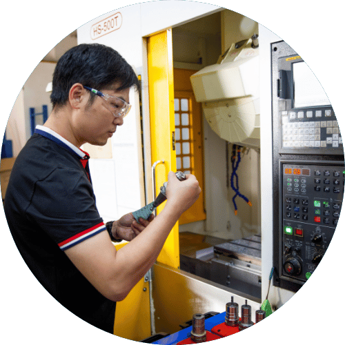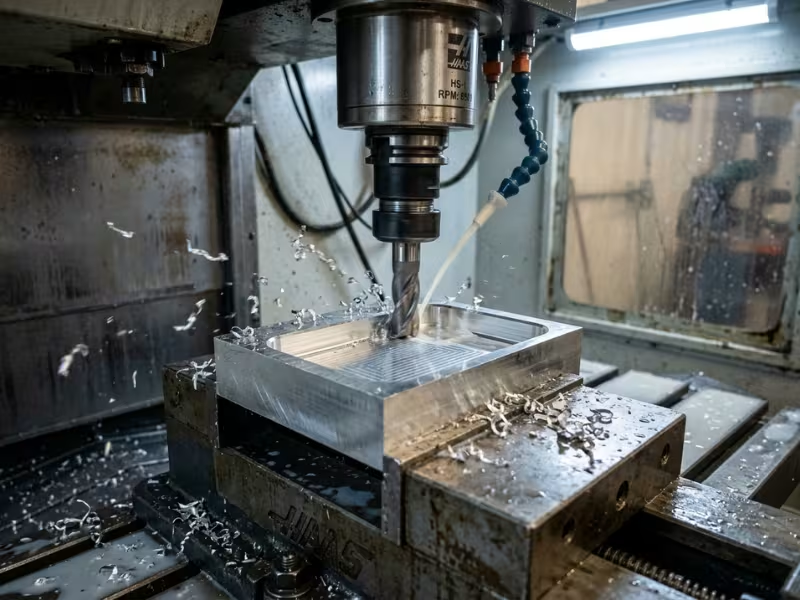
Milling removes material with a rotating cutting tool. Many people search this term because they want a clear answer, not a textbook definition.
Some readers are students. Some are buyers. Some are new machinists. Others just want to know if milling fits their part.
I usually explain milling in a simple way. The cutter spins. The machine feeds the tool or the workpiece in a controlled path. Each pass removes a small amount of material.
The best way to understand milling is not to memorize terms. It is to see what shapes milling can make, how it works, and when it makes sense to use it.
What Milling Really Means
Milling is a subtractive manufacturing process. You start with a solid block and cut away everything that isn’t the part.
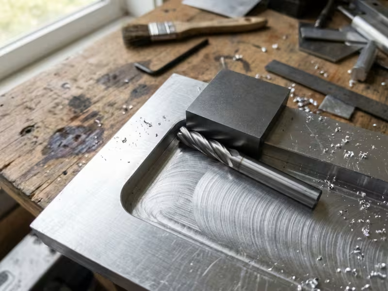
The cutter does the work. A spindle spins a tool with several sharp teeth, often at thousands of RPM. The machine then moves the cutter and the workpiece against each other. Each tooth takes a small chip as it passes. After thousands of chips, a rough block becomes a bracket, housing, or mold.
New buyers often miss one key detail. In milling, the tool rotates. The workpiece stays clamped in a vise or fixture and only moves in controlled steps.
Milling handles a wide range of materials:
- Metals such as aluminum, steel, stainless steel, brass, and titanium
- Plastics such as POM (Delrin), nylon, PEEK, and acrylic
- Composites such as carbon fiber and G10, with the right tools and dust control
The cutting principle stays the same on every type of machine. On a manual mill, an operator turns the handwheels. A CNC mill follows a programmed toolpath. A machining center adds an automatic tool changer, so one setup can mill, drill, and tap the same part.
People often mix up three related terms. Here’s how I separate them:
- Subtractive manufacturing covers any process that removes material, including milling, turning, grinding, and EDM.
- Machining means the cutting processes in that group, mainly milling, turning, and drilling. A full-scope CNC machining service typically combines all three.
- Milling is one specific method: a rotating multi-tooth cutter shaping a clamped workpiece.
All milling is machining, but not all machining is milling.
How the Milling Process Works
Every milled part comes from the same basic motion, whether it’s a simple bracket or a 5-axis impeller. Once you see how the cutter and the workpiece interact, the rest of milling makes sense.
The Basic Cutting Action
Three things happen at the same time.
- The spindle spins the cutter. A 10 mm carbide end mill in aluminum often runs at 10,000 RPM or more. Steel needs slower speeds because it creates more heat.
- The machine feeds the tool through the material. Feed rate sets how fast the cutter travels, usually in millimeters per minute.
- Each tooth takes a chip. Speed and feed together decide how thick that chip gets.
When I check a new setup, I look at the chips first. Clean, curled chips mean the tool is cutting well. Fine dust or blue, burnt chips tell me the speed or feed is off.
Depth of cut controls how much material each pass removes. Few parts come out right in one pass. I usually rough out most of the stock with heavier cuts. Then I leave about 0.2–0.5 mm for a light finishing pass. That last pass sets the final size and the CNC machining surface finish of the part.
Speed and depth aren’t the only choices that shape the result. The direction the cutter meets the material matters just as much.
Climb Milling vs Conventional Milling
A cutter can bite into the material in two ways.
Climb milling starts each chip thick and ends it thin. The tooth bites cleanly right away. You get a smoother finish, less heat, and longer tool life.
Conventional milling does the opposite. The chip starts thin and ends thick. The tooth rubs for a moment before it cuts, which builds heat and wears edges faster.
On CNC machines, I default to climb milling. Their ball screws have very little backlash, so the cutter can’t grab the part. On older manual mills with worn lead screws, climb milling can yank the table forward and snap a tool. That’s where conventional milling still earns its place. It also helps on rough castings and hot-rolled steel, since the tooth starts under the hard outer scale.
Milling vs Turning: What Spins?
People often confuse milling with turning. The fastest way to tell them apart is to ask what rotates.
|
Factor |
Milling |
Turning |
|---|---|---|
|
What rotates |
The cutter |
The workpiece |
|
What stays fixed |
Part clamped in a vise or fixture |
Tool held in a turret or tool post |
|
Typical part shape |
Prismatic: blocks, plates, housings |
Round: shafts, pins, bushings |
|
Typical features |
Flats, slots, pockets, profiles |
Diameters, tapers, grooves, threads |
My shop-floor rule is simple. If the part rolls, start with a lathe, which is where CNC turning does its best work. If it sits flat, start with a mill. Many parts need both, like a turned shaft with a milled keyway.
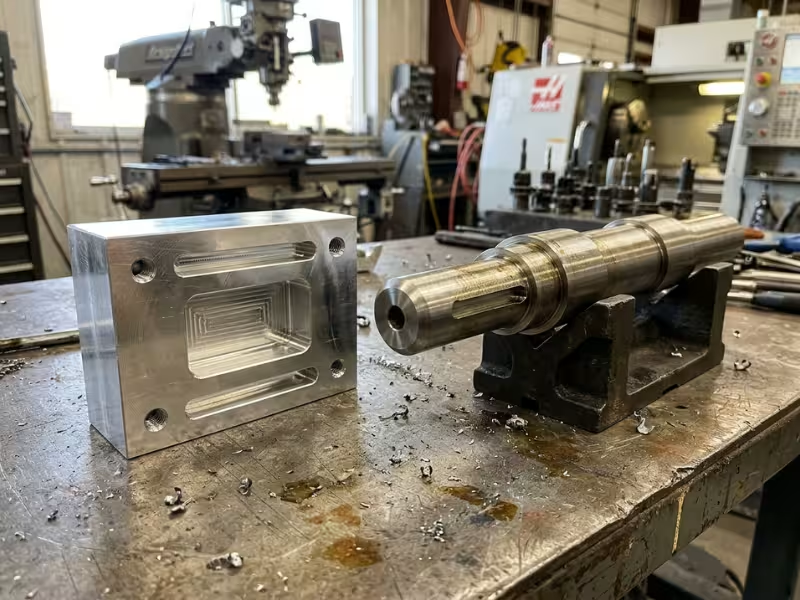
What Milling Does Best
When I review a drawing, I don’t start by asking which machine to use. I look for the features that only a mill can make. Four types show up on almost every part I quote, and each one tells you why milling earns its place.
Flat Faces and Datum Surfaces
Raw stock is never truly flat. Saw-cut plate bows a little, and castings carry rough, uneven skin. A face mill fixes that in a few passes. It leaves a clean, true surface with fine, even tool marks.
On a well-maintained machine, I can usually hold flatness within about 0.02–0.05 mm across a 100 mm face. That matters for:
- Sealing faces that must seat a gasket or O-ring
- Mounting pads that bolt flat against another part
- Datum surfaces that every other feature measures from
That last point is the one buyers miss most often. I mill the datum faces first because every pocket, slot, and hole takes its position from them. If the datum is off, everything after it is off too.
Slots, Grooves, and Pockets
A slot lets a part slide, lock, or locate. A pocket removes material inside a boundary. Both need a cutter that moves sideways, which is what an end mill does best.
Common examples include:
- Keyways that lock a gear or pulley to a shaft
- T-slots that hold clamps on fixture plates
- O-ring grooves cut to a specific width and depth
- Adjustment slots that let a bracket shift before you tighten the bolts
- Pockets for circuit boards, sensors, or simple weight savings
For slots with tight width tolerances, I rarely use a cutter that matches the slot exactly. A full-width tool tends to cut slightly oversize. I use a smaller end mill instead and finish each wall separately. That gives me direct control over the final width.
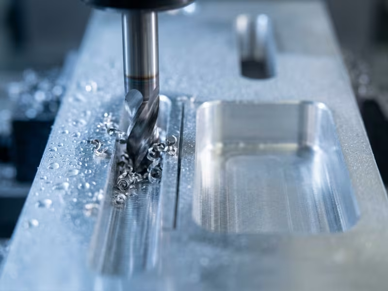
Profiles, Contours, and Non-Round Shapes
Milling can follow almost any 2D or 3D path the cutter can reach. That makes it the go-to process for outer shapes and curved surfaces.
A standard 3-axis mill handles outer profiles, chamfers, edge fillets, and openings like square cutouts or D-shaped holes. A ball end mill can step across a surface in small increments to form 3D contours, such as mold cavities or ergonomic grips. When a part has angled faces or deep undercut areas, a 5-axis machine tilts the tool to reach them without a second setup.
The tighter the stepover on a 3D surface, the smoother the finish and the longer the cycle time. I balance the two based on whether the surface needs polishing afterward.
Holes a Mill Can Handle Too
Drilling is its own process, but a CNC machining center does it without leaving the setup. The same spindle that faces the part can swap in a drill, tap, reamer, or boring bar a moment later.
This approach brings two benefits:
- Position stays consistent. Holes and milled features share one coordinate system.
- Precision holes get finished in place. I ream to fits like H7, or bore larger holes when position matters most.
For odd diameters with no standard drill, the mill can also circle-interpolate the hole with an end mill. It takes longer than drilling, but it can save you from ordering a special tool.
Common Milling Operations You Should Know
Machining catalogs list dozens of operation names. Most parts I quote rely on just five. Once you know what each one produces and when it fits, process plans and quotes become much easier to read.
Face milling cuts the top of the part flat. A wide face mill with several inserts sweeps across the surface, so one or two passes can clean up a 100 mm plate. I run it first on almost every job. It removes saw marks and mill scale, sets the part thickness, and creates the reference surface for every later feature.
End milling handles most of the remaining work. An end mill cuts with both its tip and its sides, so it can plunge, step down, and move sideways. Shoulders, steps, and side walls all come from this tool. If a vertical wall meets a floor on your part, an end mill made it.
Slot and pocket milling clears material inside a boundary. A slot runs between two points or opens at one end, like a keyway. A pocket closes on all sides, like a cavity for a circuit board. I rough these with toolpaths that keep the tool load steady, then finish the walls in a separate light pass. When you can, keep pocket depth under about four times the tool diameter. Deeper pockets need longer tools and slower feeds, and the cost rises.
Profile and contour milling follows a shape. In 2D profiling, an end mill traces the outer edge or an internal opening. In 3D contouring, a ball end mill steps across a curved surface in small increments. Smaller stepovers give smoother surfaces but longer cycle times, so I match the stepover to the finish the part needs.
Those four operations shape the part. The last pair finishes the holes.
Boring and reaming aren’t strictly milling, but most machining centers run them in the same setup. A reamer follows a drilled hole and brings it to a precise size with a smooth wall, often an H7 fit for dowel pins. A boring bar uses a single-point tool to correct both size and position. That makes it the better choice for bearing bores and large diameters.
On most milled parts, I run these operations in the same order: face, rough, shape, then finish the holes.
Where Milling Reaches Its Limits
Milling can shape almost anything, but not everything. Most redesign requests I send back to customers trace back to five limits. Spot them early, and you avoid surprises on the quote.
Inside corners always keep a radius. A round cutter can’t cut a square corner. It leaves a radius equal to its own, so a 6 mm end mill leaves a 3 mm radius. If a mating part has a sharp edge, it won’t seat. You have three options:
- Draw a corner radius slightly larger than the tool radius.
- Add a dog-bone relief.
- Pay for EDM, which often adds days.
I suggest a corner radius about 10–20% larger than the tool radius. That way, the cutter doesn’t slam into the corner and chatter.
Undercuts hide from the tool. A standard end mill cuts straight down from the spindle. It can’t reach under an overhang or behind a lip. T-slot, dovetail, and lollipop cutters handle simple undercuts. Complex ones need a 5-axis machine or a second setup. Each option adds cost, so I always ask whether the undercut truly needs to be there.
Shape is only half the story. The tool itself has limits too.
Deep, narrow pockets make tools bend. Tool stiffness drops fast as length grows. Double the stick-out, and the tool becomes roughly eight times less stiff. A long end mill flexes under load. It leaves tapered walls, chatter marks, and pockets that measure undersize at the bottom. Past about 4× the tool diameter, I slow the feed and take lighter passes. Past 6×, I ask the customer to widen the pocket or make it shallower.
Those limits show up on the part. The last two show up on the invoice.
Short runs carry the full setup cost. Before the first chip flies, someone writes the CAM program, picks the fixture, sets the tools, and checks the first part. On a moderately complex part, that can take 2–4 hours. Spread across 500 parts, it barely moves the price. On a single part, it can make up most of it. For one-offs, simple geometry and standard tool sizes help the most.
Chips are material you already paid for. Milling starts with a block bigger than the finished part. On a heavily pocketed bracket, I often turn 70–80% of the stock into chips. With aluminum, that waste costs little. Titanium costs many times more per kilogram, so the same waste hits hard. Near-net-shape blanks or forgings often make more sense there.
None of these limits rule milling out. They show you where design choices start to cost money.
When Milling Is the Right Choice
When a drawing lands on my desk, I don’t ask whether milling can make the part. It almost always can. I ask whether milling is the most reliable and cost-effective way to make it. Two quick checks usually answer that.
Signs Your Part Belongs on a Mill
Start with the features. If the part sits flat and carries faces, slots, pockets, or contours, milling usually wins. A sensor housing with a sealing lid face, an O-ring groove, and a circuit board pocket is a classic mill part. No other process makes all three in one setup.
Next, check the tolerances. Milling fits best when key features need about ±0.01–0.05 mm. A bearing seat or a dowel pattern that must line up with a datum face belongs on a mill. If every dimension can float ±0.5 mm, a faster and cheaper cutting process may do the job.
Then ask how often the design will change. Milling needs no molds or dies. When an engineer moves a pocket 3 mm in revision C, I update the CAM program in minutes. That flexibility makes milling the default for prototypes, test fixtures, and custom parts in quantities from one to a few hundred.
Milling isn’t always the best answer, though. Some parts point clearly to another process.
When Another Process Makes More Sense
Turning for round parts. If the part is mostly diameters, like a shaft, pin, or bushing, start on a lathe. A lathe cuts a long 50 mm diameter quickly in a few passes. A mill would have to circle it slowly. If the shaft needs a flat or keyway, add it afterward or use a mill-turn machine.
Laser or waterjet for flat profiles. A 3 mm steel gusset with an outline and a few holes has no depth changes. A laser can nest dozens of them on one sheet and cut them in minutes. I mill a flat part only when it needs tight hole positions, countersinks, or pockets. Waterjet suits thick plate and heat-sensitive materials.
Additive for internal complexity or very low volume. Curved internal cooling channels, lattice structures, and sealed cavities sit where no cutter can reach. Those belong to 3D printing. It also makes sense for one or two concept models where shape matters more than tolerance. Many shops combine both: they print a near-net metal part, then mill the critical faces and bores.
My rule stays simple. Match the process to the feature mix, the tolerance, and the quantity. If the part has flat references, mixed features, and real tolerances, milling earns the job, and a dedicated CNC milling service is the right place to send it.
What Drives Milling Cost
Customers often ask me why two parts of the same size get very different quotes. The answer rarely comes down to material price. It comes down to hours in the shop, and your drawing decides most of those hours.
Here’s what I look at when I build a milling quote:
- Machine time. Shops bill spindle time by the hour. A 5-axis machine usually bills well above a 3-axis mill. Every extra minute of cycle time repeats across the whole batch.
- Setup and fixturing. Each time an operator flips a part, they clamp it, indicate it, and check it again. That often takes 30–60 minutes per setup. A custom fixture adds more on top.
- Programming. CAM work costs the same for one part or 1,000. A simple plate might take an hour. A 3D contoured part can take a full day.
- Tool wear. An end mill can run for hours in aluminum. Stainless steel and titanium dull the same tool much faster, and those replacement tools show up in your price.
- Material difficulty. Hard or gummy metals force slower speeds and lighter cuts. A pocket that takes 5 minutes in 6061 aluminum can take 20 minutes or more in 316 stainless.
Rates and materials set the baseline. Four design choices decide how far above it your quote climbs.
Design around standard tools. Size corner radii and slot widths to common cutters, such as 3, 6, 10, or 12 mm. A 4.3 mm slot forces a smaller tool and extra passes. An odd radius can require a special cutter with a long lead time.
Reduce setups. Put features on as few faces as you can. If every pocket and hole opens from the top, I can often finish the part in one clamping. Features on five sides may need five setups or a pricier 5-axis machine.
Avoid deep, narrow features. A 3 mm slot that runs 20 mm deep needs a long, thin tool. I run it at a fraction of normal feed, and it can still snap. Widening that slot to 6 mm can cut its machining time roughly in half.
Keep tight tolerances for features that need them. A ±0.01 mm callout means slower finishing passes, more tool checks, and extra inspection. A clearance hole or an outside edge works fine at ±0.1 mm. I regularly see quotes drop by 20% or more after a customer relaxes tolerances on non-critical features.
Before you send a drawing, check those four points. They cost nothing to change in CAD, and they often save the most on the quote.
Milling Machines in Simple Terms
Buyers often ask me which machine will make their part. Most of the time, the part’s features answer that question. Three simple splits cover almost every mill you’ll find on a shop floor.
Manual or CNC. On a manual mill, an operator turns handwheels and reads dials. I still use one for one-off fixes, quick repairs, and simple jobs where writing a program would take longer than cutting the part. A CNC mill follows a programmed toolpath instead. It makes the same cut on part 1 and part 500, and it can trace curves and 3D surfaces that no hand could follow.
Vertical or horizontal. Most shops run vertical machining centers. The spindle points down, setup is quick, and the operator can see the cut. A horizontal machine turns the spindle sideways. Chips fall away from the part instead of piling up in pockets, so it handles deep side cuts and heavy material removal well. Many horizontals also use pallet changers and multi-sided fixtures, which suit high-volume production.
3-axis or 5-axis. A 3-axis mill moves the tool in X, Y, and Z. It handles most prismatic parts, such as plates, brackets, and housings with features on one or two faces. A 5-axis machine adds two rotary axes, so it can tilt the tool or the part. It reaches angled holes and side features without a new setup. That cuts handling and keeps features aligned, but the hourly rate runs higher.
My advice is simple. Describe your features and tolerances clearly, and let the shop match the machine to the job.
Milling FAQ
What is milling in simple terms?
Milling uses a spinning cutter to carve material away from a clamped block. The machine moves the tool along a set path, and each pass shaves off small chips. What remains becomes the part, such as a flat plate, a bracket, a housing, or a mold.
What is the difference between milling and drilling?
Drilling makes round holes. The drill feeds straight down along one axis, and the drill’s diameter sets the hole size.
Milling makes shapes. An end mill cuts mostly with its sides and moves in X, Y, and Z to create flats, slots, pockets, and profiles. Most CNC machining centers do both in the same setup. On a typical part, I mill the features and drill the holes without unclamping.
What is the difference between milling and turning?
Ask what spins. In milling, the cutter rotates and the part stays clamped. In turning, the part rotates and a fixed tool cuts it.
That difference decides the shape. Mills suit flat, blocky parts like plates, brackets, and housings. Lathes suit round parts like shafts, pins, and bushings.
What materials can be milled?
You can mill almost any solid material you can clamp securely. I mill aluminum, steel, stainless steel, brass, copper, and titanium every week. Plastics such as POM, nylon, PEEK, and acrylic cut well with sharp tools and controlled heat. Composites like carbon fiber and G10 also mill cleanly with the right cutters and dust control.
Harder metals force slower speeds and wear tools faster, so they cost more to machine.
How much does CNC milling cost?
Shop time drives the price more than material does. Many shops bill 3-axis work at roughly $50–$120 per hour, and 5-axis work runs higher.
A one-off part carries the full setup and programming cost, so even a simple bracket can cost a few hundred dollars. At 500 pieces, the same bracket often costs a small fraction of that per part. Standard tool sizes, fewer setups, and relaxed tolerances on non-critical features lower almost any quote.
What tolerance can milling achieve?
A standard CNC mill holds about ±0.05–0.1 mm on general features without special effort. With finishing passes, sharp tools, and careful setup, I hold ±0.01–0.02 mm on critical features like bearing seats and dowel positions.
Shops can go tighter, but each step down adds inspection time and cost. Call out tight tolerances only where the part’s function needs them.
Start With the Part, Not the Machine
Milling uses a spinning cutter to carve flats, slots, pockets, and profiles from a clamped block.
Before you pick a process, check three things. Look at the geometry, the material, and the quantity. Those answers tell you more than any machine name ever will.
Here’s what I see every week. The best quotes come from drawings where each feature matches what the process does well.
So open your drawing and sort every feature. Then send it to your machining partner with clear tolerances. You’ll get a sharper quote and parts that fit the first time.