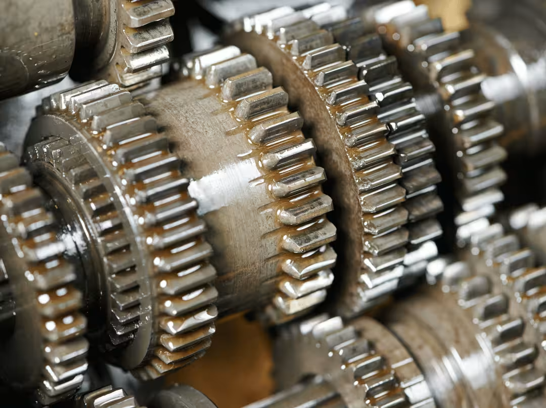
A car transmission drops into third gear under hard acceleration, and hundreds of tooth contacts share that load without a whisper. Gear manufacturing is what makes that possible — and it’s almost never a single process. The same gear print can be produced five different ways, and choosing the wrong route doesn’t just cost money. It can mean accuracy you paid for but never needed, or a batch scrapped because heat-treatment distortion was not accounted for.
That’s the real risk. A gear that looks simple on paper hides a chain of linked decisions: how to make the blank, how to generate the teeth, whether and how to harden, how to finish after distortion, and how to verify the result. Every link affects the next.
This guide doesn’t sweep every process like a textbook. It shows you how each process fits, where it wins, where it fails, and how to apply a reliable selection logic to your geometry, volume, and accuracy class.
The Gear Manufacturing Chain at a Glance
Before any single process makes sense, you need the mental model. Every gear — from a plastic appliance pinion to a hardened truck transmission gear — passes through the same five stages:
- Blank preparation — turning, forging, or casting the raw body
- Tooth generation — creating the actual gear teeth
- Heat treatment — hardening for wear and load resistance
- Finishing — restoring accuracy after distortion
- Inspection — verifying geometry against a class standard
The stage that splits into two fundamentally different worlds is tooth generation. Cutting removes chips to generate the teeth; forming presses, casts, molds, or sinters the tooth shape without removing material. That fork drives almost every downstream decision — cost, volume, strength, and the number of later stages the chain requires.
Here’s the rule that runs through the rest of this article: loose accuracy classes may skip finishing entirely, while tight classes force grinding or honing after hardening. The accuracy spec on your print sets the length of the whole chain. A gear that tolerates a modest quality class might go straight from cutting to inspection. A precision gear may pass through all five stages — with an extra machining step added after heat treatment.
Gear Types and Specs That Actually Change the Process
You don’t need a gear taxonomy lecture to choose a process. You need to know which geometry decisions and print callouts actually shift the machine you’ll use.
Gear Geometry Decides the Machine
Think about gear types by how they constrain manufacturing, not how they’re defined in a textbook. Before volume or cost enters the conversation, geometry has usually already narrowed your options:
- External spur and helical gears → hobbing territory
- Internal and cluster gears → shaping or broaching
- Bevel, miter, and hypoid gears → specialized generators
- Worm and worm wheel sets → hobbing with special tooling
- Rack and pinion → its own dedicated setup
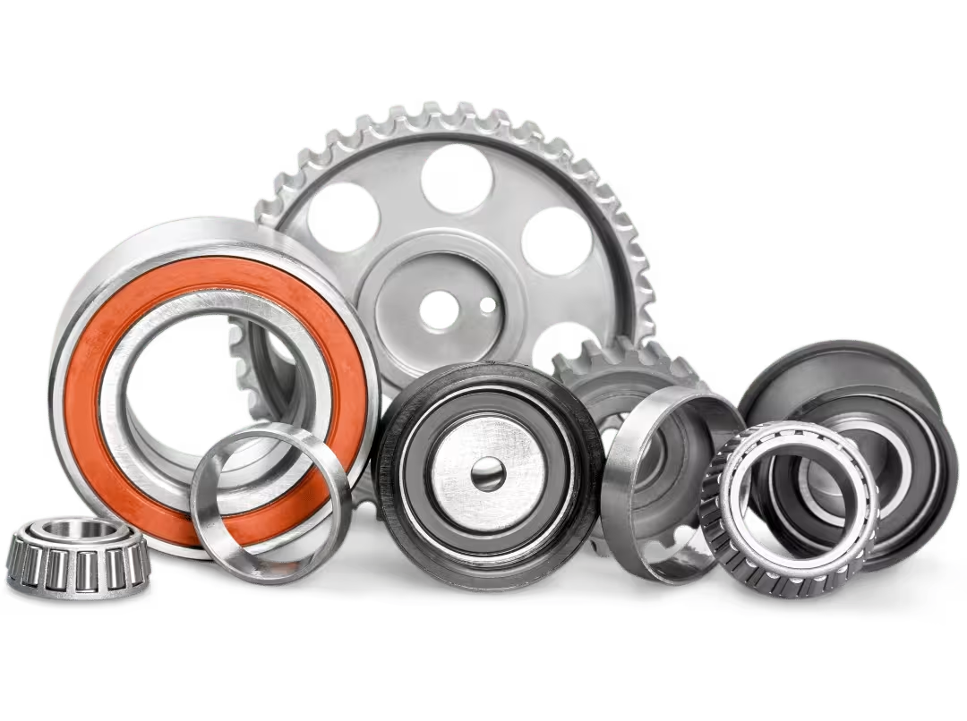
If a gear is internal, hobbing is off the table before you even discuss volume. Geometry is that decisive.
The Print Callouts That Drive Cost
Only a handful of specs actually shift the route: module or diametral pitch, pressure angle, helix angle, and — above all — the accuracy class, expressed as an AGMA quality number or an ISO 1328 tolerance grade. Nearly all power gears use an involute tooth profile because it delivers smooth, constant-velocity transfer even when center distance drifts slightly. Worth knowing, but not a decision point.
The callout that quietly controls your budget is the accuracy class. A tighter class means more finishing steps, and more finishing steps mean more cost. That single number often dictates the entire process chain — treat it as a cost lever, not a formality. Face width, root clearance, and similar details are things your supplier needs to machine the part, not inputs that flip the process selection.
Gear Materials and Blank Preparation
Material choice does two things at once. It narrows the process before performance calculations even begin, and through the quality of the blank, it sets a hard ceiling on the accuracy every downstream step can reach.
Matching Material to the Process
Keep material selection tied to the application, not to a metallurgy textbook:
- Carbon steel (e.g., 1045) — moderate loads, light hardening requirements
- Alloy steel (8620, 4140) — the transmission workhorses; respond well to carburizing or through hardening
- Stainless steel — where the environment demands corrosion resistance
- Bronze and brass — worm gears that need low friction and quiet running
- Cast iron — large gear bodies where damping and compressive mass matter
- Engineering plastics (acetal, nylon, PEEK) — light-duty, low-noise, high-volume applications
Material quietly eliminates whole process families before the selection conversation begins. Powder metallurgy and injection molding only work with compatible materials. Hobbing and grinding handle most metals. Specify a plastic gear, and you’ve already pointed at CNC plastic machining or molding. Specify a carburized alloy steel and you’ve committed to a cut-plus-heat-treat chain, with grinding almost certainly to follow. The mistake people make here is treating material as a downstream detail — it’s one of the first filters.
Why the Blank Sets Your Ceiling
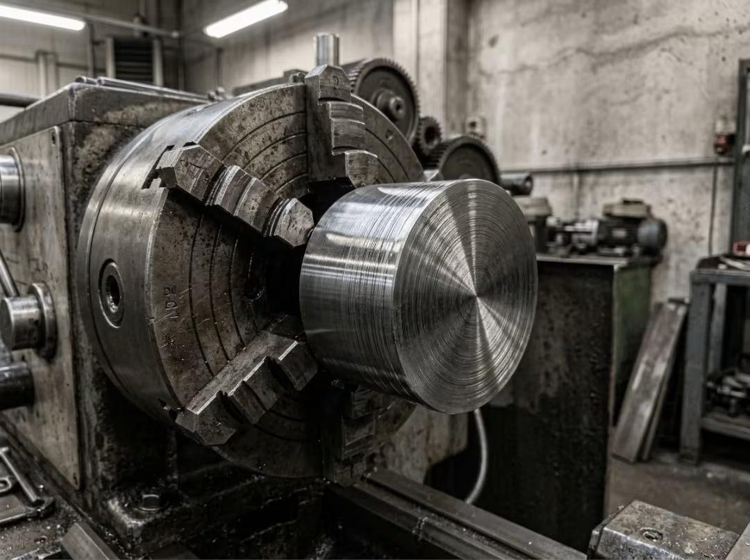
The blank is the raw body before any teeth exist. It arrives by one of three routes: turned bar stock (faced, bored, and turned to size) for most small and medium gears; forged blanks for high-strength applications where grain flow following the tooth form matters; or cast blanks for very large gears or complex hub geometry.
The rule too many teams learn the hard way: blank accuracy caps final gear accuracy. Bore runout and face squareness carry straight into tooth error, and no amount of hobbing precision or grinding time can fix what the blank introduced. Prep the bore, keyway, and splines carefully before tooth cutting. You can’t grind your way out of a crooked blank.
Cutting vs Forming: The Fork That Shapes Everything
All the decisions above funnel into one axis: do you remove material to generate the teeth, or displace it? That single choice maps directly to volume, cost, and process chain length.
Cutting generates teeth by removing chips. It’s flexible, accurate, and tolerant of complex geometry — but slower and more material-wasteful. It wins at low-to-medium volume and where tight geometry control is non-negotiable.
Forming presses, casts, molds, or sinters the tooth shape. It’s fast, produces little scrap, and can build favorable grain flow into the part. Tooling costs are high and geometry options are narrow. It wins decisively at volume.
One more line belongs here because it governs every finishing decision that follows: soft cutting happens before hardening; hard cutting happens after hardening. Cut before heat treatment makes the part easier to machine, but distortion from hardening will likely require a finishing step. Cut after hardening — grinding being the primary example — and you’re correcting what heat treatment warped. That before-or-after choice threads through everything that follows.
Gear Cutting Processes: Hobbing, Shaping, Milling, and Broaching
Four cutting processes account for the vast majority of gears produced. Each has a clear signature — not just in how it works, but in when it’s the right call and when reaching for it is a mistake.
Gear Hobbing
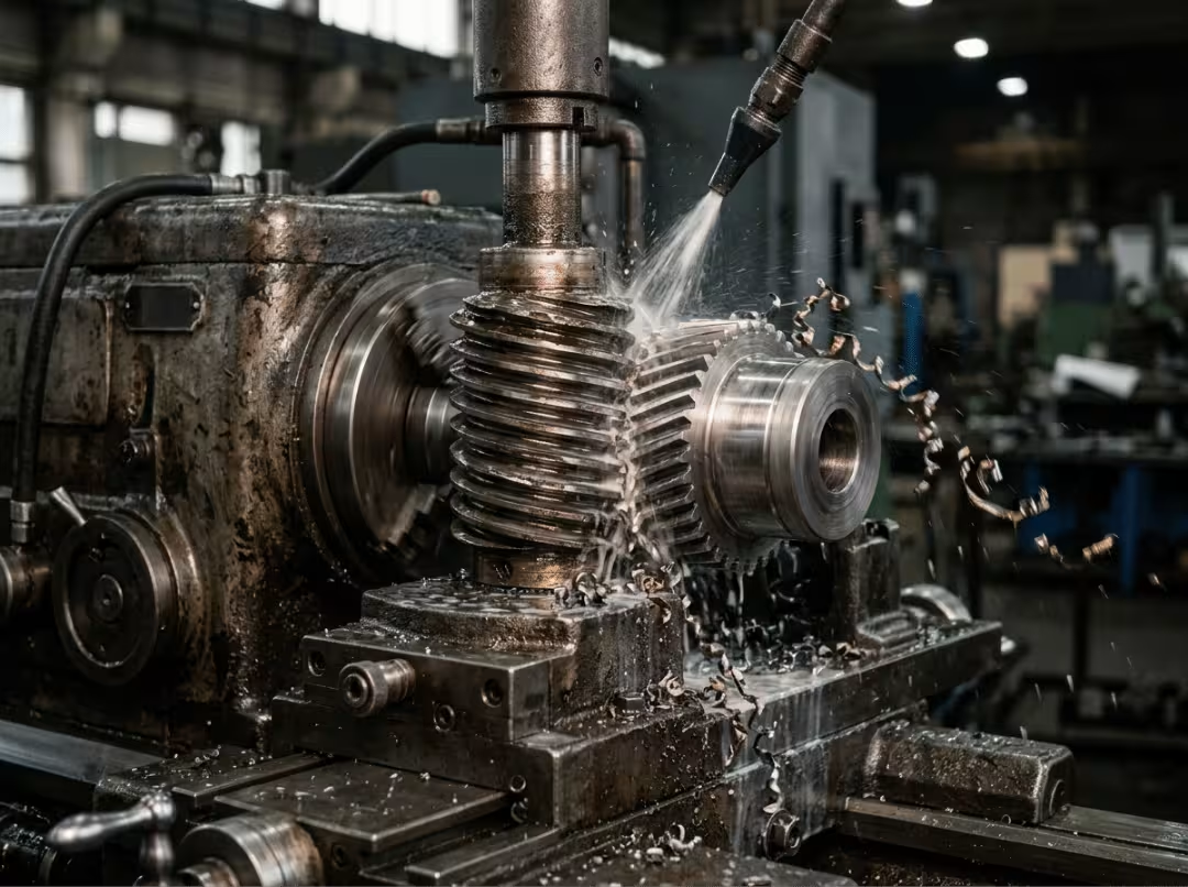
A worm-shaped hob rotates in timed sync with the blank, generating the involute profile in a single continuous pass. It’s the default for external spur and helical gears and the backbone of high-volume automotive and industrial production. Cycle times are fast, accuracy is good, and tooling cost is moderate.
Hobbing’s limit is reach. It can’t cut internal gears, and it struggles with teeth that sit right against a shoulder. Choosing hobbing for a cluster gear or a gear with a blocking flange is a common and costly mistake.
Gear Shaping
A pinion-shaped cutter reciprocates while rolling against the blank, cutting one stroke at a time. Shaping is the right answer when hobbing physically can’t reach — internal gears, cluster gears, and gears adjacent to shoulders. It’s slower on a simple external gear, but that’s usually the wrong comparison to make. Compare it against the parts it was built for: planetary ring gears, stepped transmission gears, anything with an obstruction nearby.
Gear Milling
A form cutter carves one tooth space at a time using a milling machine and an indexing setup. Setup cost is low, and changeover is quick, which makes milling the practical choice for prototypes, one-offs, oversized gears, and field replacement parts. Productivity and accuracy are lower than hobbing or shaping, so it doesn’t belong in a production run. The risk here is using milling because it’s available and familiar, rather than because it suits the part.
Gear Broaching
A long, toothed tool is pushed or pulled through the blank, cutting internal teeth in a single pass. Broaching is fast, accurate, and repeatable — the go-to for high-volume internal gears and splines. The barrier is tooling cost: broaches are expensive to make, so the process only makes economic sense at volume. Using broaching for small runs is a common budgeting error that looks obvious in hindsight.
How the Cutting Processes Compare
|
Process |
Gear Types Handled |
Typical Accuracy Range |
Relative Tooling Cost |
Best Volume Range |
|---|---|---|---|---|
|
Hobbing |
External spur, helical, worm |
Good to high |
Moderate |
Medium to high |
|
Shaping |
Internal, cluster, shouldered |
Good to high |
Moderate |
Low to medium |
|
Milling |
Most types, including oversized |
Low to moderate |
Low |
One-offs to low |
|
Broaching |
Internal gears, splines |
High |
Very high |
High only |
The pattern is consistent: hobbing is the volume default, shaping solves access problems hobbing can’t, milling handles the odd jobs and prototypes, and broaching earns its cost only at scale.
Gear Forming Processes: Rolling, Casting, Forging, Powder Metallurgy, and Molding
Forming makes the opposite tradeoff from cutting. You give up geometry flexibility in exchange for speed and low cost at volume. Each method has a specific sweet spot — and a specific type of part it handles poorly.
Gear Rolling
Cold rolling presses toothed dies into a rotating blank, displacing metal into the tooth cavities. The result is a smooth, work-hardened surface with better fatigue strength than a cut equivalent — which is why it’s common for splines and pinion shafts. Hot rolling handles larger gears where cold rolling forces would be too high. Rolling can’t reproduce every profile, so check geometry compatibility before committing to the tooling.
Best suited for: high-fatigue applications on rollable profiles at volume.
Gear Casting
Sand casting works for large, low-volume gears. Investment casting gets closer to net shape with better surface detail. Die casting handles small aluminum or zinc gears at high volume. In all three cases, as-cast teeth almost never meet precision requirements on their own — follow-up machining is the rule, not the exception. Use casting when the gear is large, the hub geometry is complex, or machining from solid is clearly prohibitive.
Gear Forging
Closed-die forging produces near-net teeth with continuous grain flow, raising strength and toughness well beyond cut-from-bar equivalents. Almost every forged gear is still machined or shaved afterward to achieve final accuracy. Forging is the standard route for heavy-duty automotive and truck transmission gears precisely because no other process reliably delivers that combination of strength and near-net form at scale.
Powder Metallurgy
Metal powder is pressed into a die and sintered to bond the particles. Scrap is minimal, repeatability is high, and per-part cost is low — which is why powder metallurgy dominates in medium-size gears at high volume, such as in appliance and power tool applications. The tradeoff is strength: sintered parts run lower than wrought steel. Any application with heavy loads needs either a secondary treatment or a different process. Specifying powder metallurgy for a high-load gear because it’s cheap upfront is a well-documented mistake.
Plastic Gear Injection Molding
Injection molding is the lowest cost-per-part route at very high volume for acetal, nylon, or PEEK gears. It offers quiet operation, corrosion resistance, and self-lubricating options. The challenge is tooth accuracy — shrinkage, gate location, and cooling rate all affect the final tooth form and must be engineered into the mold from the start, not corrected afterward. The upfront mold cost is significant, so the process only makes sense when volume is high enough to amortize it. For lower volumes, machined plastic is often the more practical path.
Gear Heat Treatment: Buying Hardness Without Losing Accuracy
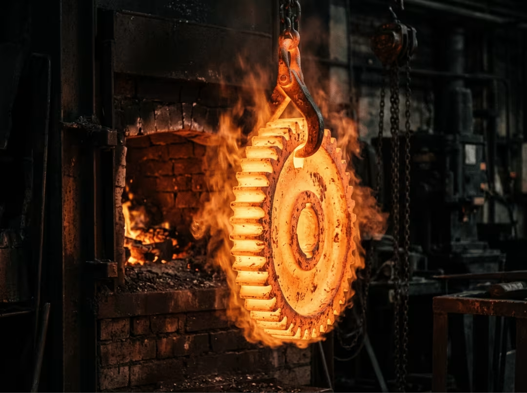
Every precision gear eventually faces the same trade-off: tooth flanks require hardness to resist wear, and the core requires toughness to withstand shock loads. Heat treatment buys you both. The cost is geometry. Hardening distorts the part — sometimes slightly, sometimes substantially — and that distortion is the primary reason process chains get longer.
Choose the method by what it needs to accomplish:
|
Process |
Case vs Through |
Distortion Level |
Typical Use |
|---|---|---|---|
|
Through hardening |
Through |
Moderate |
Uniform hardness, medium-carbon alloy steel |
|
Carburizing |
Case |
High |
Heavy bending loads; classic for 8620 |
|
Carbonitriding |
Case (shallow) |
Moderate |
Lower-temperature, shallower-case applications |
|
Nitriding |
Case (thin) |
Very low |
Gears already finish-machined; minimal distortion needed |
|
Induction hardening |
Case (targeted) |
Low to moderate |
Flank and root hardening on medium-carbon steels |
Through hardening quenches and tempers a medium-carbon alloy for uniform hardness across the cross-section. Carburizing adds carbon to the case and then quenches — the standard choice for 8620 under heavy bending, where a tough core matters as much as a hard surface. Carbonitriding is a lower-temperature carburizing variant that adds nitrogen, yielding a shallower case with slightly less distortion. Nitriding creates a hard, thin case without a quench, making it the right pick for gears that are already finish-machined and have tight distortion tolerance. Induction hardening heats only the flanks and roots and then quenches — fast, targeted, and well-suited to medium-carbon steels in volume production.
Whichever method you use, the production reality is the same: hardening warps the gear, so precision parts need grinding, honing, or lapping afterward. This is the single biggest reason a five-stage chain has to exist.
Gear Finishing: Restoring the Accuracy Hardening Took Away
Finishing is not the final polish on an otherwise complete part. For tight-class gears, it’s where the actual tolerance is achieved — after cutting errors and heat-treat distortion have both taken their toll. The right method depends on when in the sequence it happens and what problem it’s solving.
Gear Shaving (Before Hardening)
A shaving cutter scrapes microscopic chips from soft, unhardened teeth, removing errors left by hobbing or shaping and improving surface finish. Shaving is always done before heat treatment — hardened teeth are too hard to shave. It doesn’t add to the hardened part; it cleans up the soft part before the hardening step locks in its shape. Shaving a gear you plan to grind afterward is generally not worth the cost.
Gear Grinding (After Hardening)
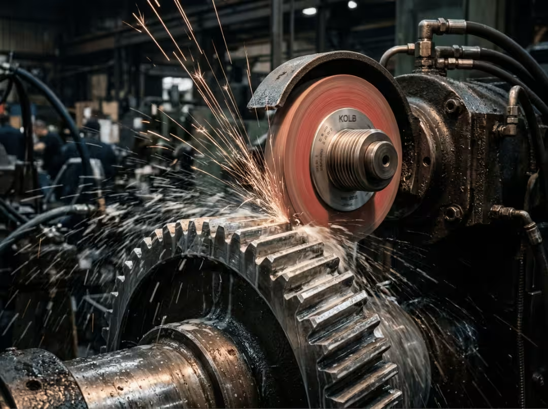
Grinding comes in two main forms: form grinding, which uses a shaped wheel that matches the tooth profile, and generating grinding, which uses a threaded or worm wheel to roll-generate the involute. Both work on hardened gears and correct most heat-treat distortion. Grinding is the highest-precision option available and the standard process for automotive final drives and precision industrial gears. The flanks it produces are also the quietest in service.
The cost is real. Gear grinding machines and wheels are expensive, setup is time-intensive, and cycle times are longer than soft-cutting. Grind only where the accuracy class demands it. Over-grinding is a budget drain that delivers no measurable value when the spec doesn’t require it — and if you’re unsure what surface finish your application actually needs, that’s worth determining before making the grinding decision.
Gear Honing (After Hardening)
An abrasive hone runs in mesh with the hardened gear, removing a thin layer of material. Honing is particularly good at correcting light heat-treat distortion and leaves a crosshatch surface pattern that holds lubricant well during running. In automotive production lines, honing often appears as the final step after grinding — a relatively quick operation that improves both geometry and surface texture.
Gear Lapping (After Hardening)
Fine abrasive compound is worked between the gear and a lap or mating gear. Lapping is primarily used on bevel and hypoid gears where the contact pattern, not dimensional accuracy, is the target. It removes almost no material and won’t fix a size error. Using lapping to try to correct a geometry problem it wasn’t designed to solve is a common and frustrating mistake — one that delays production without improving the result.
Mechanical Surface Treatments
Shot peening blasts steel shot onto the tooth surface, inducing compressive residual stresses that substantially improve fatigue life — particularly at the root, where bending fatigue initiates. Burnishing rolls out surface micro-roughness without removing material. Neither process changes tooth geometry. They improve surface properties only, and that distinction matters when you’re deciding where in the sequence they belong.
Gear Inspection and Quality Control
Gear quality is a geometry problem, not just a materials problem. A gear made from the right steel, carburized correctly, and ground on a good machine can still fail inspection if the geometry drifted at any stage. The standard is a class number, not a gut feel.
The measurements that define whether a gear meets spec: profile, lead, pitch, runout, and tooth thickness. The tools that verify them:
- Gear measuring machines and CMMs — full geometric analysis against the print
- Roll testers — a functional check of how the gear runs under near-operating conditions
- Dial indicators — fast runout checks on the production floor
- Contact-pattern analysis — essential for bevel and hypoid gears, where the contact zone position drives both strength and noise
Standards give these measurements meaning. AGMA quality classes and ISO 1328 tolerance grades describe how tight the gear must be, and committing to a class number commits you to a corresponding level of process cost. Move one class tighter, and you’re often adding a finishing step and a more rigorous final inspection. That escalation rarely surprises experienced teams — but it consistently catches buyers who default to the tightest class without understanding what they’re purchasing.
Smart operations split inspection into two phases: in-process checks during hobbing and grinding, and a final inspection in a temperature-controlled lab. The defects to catch along the way are specific: nicks, burrs, grinding burns, soft spots in the case, case-depth variation, and runout that built up through the process chain.
How to Choose the Right Gear Production Process
Every section above feeds into this one. Instead of memorizing individual processes, run your part through five filters in order. Most selections resolve within the first three.
Run the Part Through Five Filters
- Geometry. Internal or cluster gears go to shaping or broaching. Bevel and hypoid gears need specialized generators. Worm gears need to be hobbed with appropriate tooling. External spur and helical gears default to hobbing. Geometry eliminates options before anything else.
- Material. Hardened steel forces a cut-plus-heat-treat-plus-grind chain. Engineering plastics point to injection molding. Large, complex gear bodies point to casting or forging. Material narrows the process families before you run a cost analysis.
- Volume. One-offs and prototypes favor milling or casting. Medium production runs favor hobbing or shaping. High volume favors rolling, powder metallurgy, or injection molding. Volume determines whether front-loaded tooling cost is ever recovered.
- Accuracy class. The tighter the AGMA or ISO class, the longer the process chain. At the tightest classes, grinding is not optional — it’s what makes the class achievable. This filter frequently overrides a process choice that looked economical under filters one through three.
- Total cost, not piece price. Tooling — dies, hobs, molds, broaches — is front-loaded. Per-part cost plays out across the product’s life. A cheap piece price behind expensive tooling only makes financial sense at volume. Map both before committing.
Three Worked Examples
- Automotive transmission gear: hobbing to generate teeth efficiently at volume, carburizing for a hard case and tough core, then grinding to restore accuracy after the hardening step.
- Small appliance gear: powder metallurgy or injection-molded plastic, selected for low per-part cost at high volume where load demands are modest.
- Large wind turbine gear: a cast or forged blank — because machining from solid is impractical at that size — followed by CNC metal machining and grinding to meet the precision class the application demands.
Walk any gear through the same five filters, and you’ll land near the same answer the examples do.
Decisions That Cost the Most
Over-specifying accuracy is the most common expensive mistake — paying for grinding when the application never required the tighter class. Close behind it is ignoring heat-treat distortion: teams that lock in a process before understanding how hardening will affect their geometry often discover the problem at final inspection, not during planning. The third error is committing to a single process before the full chain — blank through inspection — is defined. A process that looks right for tooth generation can be wrong once you factor in blank prep, heat treatment options, and finishing requirements.
Frequently Asked Questions
What is the most common gear manufacturing process?
Gear hobbing. For external spur and helical gears, it’s the default in most production environments — fast cycle times, good accuracy, moderate tooling cost, and broad applicability across industrial and automotive volumes.
What is the difference between gear hobbing and gear shaping?
Hobbing uses a continuously rotating worm-shaped hob and is best for external gears produced at volume. Shaping uses a reciprocating pinion cutter and is the right choice when hobbing can’t physically reach — internal gears, cluster gears, and teeth immediately adjacent to a shoulder or flange.
Why are gears heat treated after cutting?
To build a hard surface that resists wear while keeping a tough core that absorbs shock. Cutting comes first because soft metal is far cheaper and faster to machine. Heat treatment after cutting is also what introduces distortion, which is why precision gears require finishing afterward.
What is the difference between gear grinding and gear shaving?
Shaving works on soft, unhardened teeth before heat treatment, removing small errors left by hobbing or shaping. Grinding is performed on hardened teeth after heat treatment, correcting the distortion introduced by hardening and achieving the tightest accuracy classes. They address different problems at different points in the chain.
How are bevel gears made?
On specialized generating machines designed for angled tooth geometry — face hobbing and face milling are the two primary methods, each producing a slightly different tooth geometry. High-precision bevel and hypoid gears are then lapped or ground to refine contact pattern and noise behavior.
What is the difference between soft machining and hard machining?
Soft machining is any tooth-generation process — hobbing, shaping, milling — performed before heat treatment while the metal is still relatively easy to cut. Hard machining is any process performed after hardening, primarily grinding and honing, whose goal is to correct distortion rather than generate the initial tooth form.
Which gear manufacturing process is cheapest for high volumes?
For metal gears, powder metallurgy typically delivers the lowest cost per part at high volume, provided the load requirements remain within the sintered material’s strength limits. For light-duty gears, injection-molded plastic costs less — but only once the mold tooling is fully amortized over a sufficiently large production run.
Conclusion: Match the Process to the Part
There’s no universal best process for manufacturing gears. There’s only the right chain for a specific gear’s geometry, material, volume, and accuracy class. Cutting offers flexibility and precision. Forming offers speed and cost efficiency at volume. Heat treatment and finishing exist because hardness and accuracy rarely come from the same step — and ignoring either one produces a part that fails in a predictable way.
Before you shortlist a supplier, pull the print and note two things: the accuracy class and the annual volume. Map the full chain from blank through inspection. A small change in either number can shift the optimal process entirely — which is precisely why defining requirements up front costs far less than redesigning a process chain mid-production.