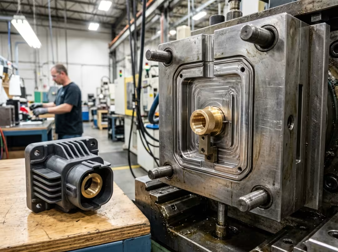
Insert molding builds a metal-and-plastic part in a single operation. A metal insert goes into the mold, plastic is injected around it, and the result is one bonded component—no screws, no adhesives, no downstream press-fit station. That’s the whole point: it eliminates an assembly step.
This guide covers how insert molding works, when it makes more sense than the alternatives, and how to design the insert and select the right plastic so the part holds up in real service—not just off the machine. The mechanics are straightforward. The judgment is where it gets interesting: when to use it, when not to, and why parts sometimes crack six weeks after they ship. If you’re also evaluating broader production options, Essengold’s CNC machining service covers the full range of precision metal and plastic work.
What Insert Molding Is
Insert molding—sometimes called metal insert molding—is an injection molding process in which a preformed insert, almost always metal, sits in the mold cavity while plastic is injected around it. Once the plastic solidifies, you have one bonded part. No second operation. The bond forms during the shot.
The purpose is to remove secondary assembly and build structural strength into the part while it’s being made. Rather than molding a plastic housing and then pressing or gluing metal hardware into it, you put the metal into the mold and let the plastic do the joining.
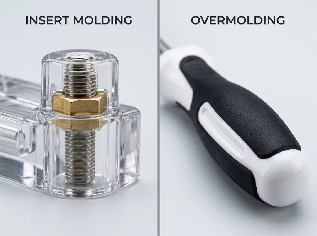
People often mix this up with overmolding, but they’re different. Insert molding wraps plastic around a non-plastic preform. Overmolding wraps plastic around a pre-molded plastic base. A threaded brass insert locked inside a plastic bracket is an example of insert molding. A soft rubber grip bonded over a hard plastic handle is overmolding. Same machine family, different logic.
Common inserts are threaded brass, steel, stainless steel, and aluminum, with ceramic or printed circuit boards appearing in more specialized applications. Brass and stainless dominate because most applications require threads, electrical contact, or both.
How It Works
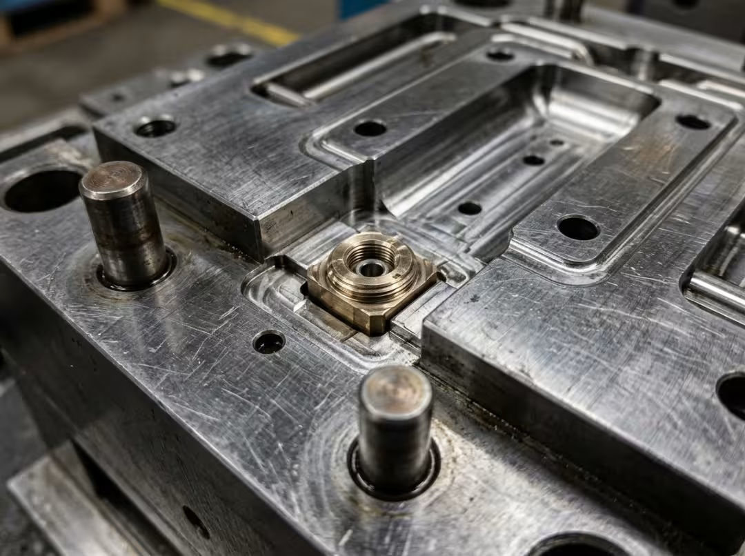
The insert loads into the mold cavity first. At low volumes, an operator places it by hand; at high volumes, a robot handles it. Either way, the insert must sit precisely on locating pins or in seating features, because what follows is a shot of high-pressure molten plastic that will move anything not firmly held in place.
The mold closes, and plastic injects under pressure, flowing around the insert and into its knurls, grooves, and undercuts. That’s when the mechanical lock forms—plastic fills every retention feature and takes on the exact geometry of the insert’s surface.
Then the part cools. As the plastic solidifies, it shrinks, which tightens the grip on the insert. This isn’t a side effect to work around—it’s the mechanism that makes the bond work. A well-designed insert converts cooling shrinkage into clamping force. A poorly designed one converts it into crack-initiation stress.
After ejection, trimming, inspection, and thread cleaning happen as needed.
Two moments decide whether a part succeeds. The insert can’t shift during injection—any movement produces uneven walls, lost tolerances, and a weaker lock. And the plastic has to grip cleanly as it cools. Most of the design decisions in the next section exist to protect those two moments.
When to Use Insert Molding vs. the Alternatives
Say you need a metal feature—a thread, a contact, a pin, a sleeve—inside a plastic part. Insert molding is one of four ways to get there, and it isn’t always the right one.
Versus traditional injection molding plus assembly. Standard injection molding produces an all-plastic part, then a separate operation presses, stakes, or fastens the metal in afterward. Insert molding collapses both into one cycle: you trade a slower mold cycle for zero downstream assembly—less labor, less handling, one fewer place for things to go wrong.
Versus press-fit inserts. Press-fit inserts get pushed into pre-molded holes after the plastic is formed. Simpler tooling, faster cycle, no insert to manage during the shot. The weakness is pull-out and push-out resistance—the plastic never forms around the retention features, so mechanical engagement is shallower. For light-duty threads that rarely see load, that’s acceptable. For anything torqued repeatedly or under cyclic stress, it becomes a real liability.
Versus ultrasonic or heat-staked inserts. These melt plastic around the insert after molding, using vibration or heat. The bond is solid, and the approach is flexible—useful when the design is still evolving, and you don’t want to commit to expensive tooling yet. But it’s still a secondary operation with its own equipment, cycle time, and process variables to manage.
The honest trade-off: insert molding delivers the strongest bond and eliminates assembly entirely. The cost is a slower cycle, more complex tooling, and a wasted insert every time a part is rejected. Post-mold methods win when volumes are low, designs are still in flux, or the strength requirements are modest enough that simpler approaches cover it.
A practical decision cue:
- High volume + high pull-out demand + stable design → insert molding
- Low volume or an evolving design → press-fit or ultrasonic
Two examples make the contrast clear. A threaded brass insert in a high-volume electronics housing—design locked, running hundreds of thousands of parts, threads torqued on every assembly—is a strong case for insert molding. The tooling is amortized across the run, and the assembly savings accumulate quickly. Now consider a prototype housing that may change three more times before production. Committing to insert-molding tooling there makes no sense. Use a press-fit or ultrasonic insert, iterate cheaply, and lock the design before investing in tooling.
Designing the Insert and Pairing Materials
This is where parts actually succeed or fail. Good molding can’t rescue a badly designed insert, and it can’t fix a poor material pairing. Both problems produce the same symptoms—cracks, loose inserts, field returns—and neither responds to process tuning.
Insert Design That Actually Holds
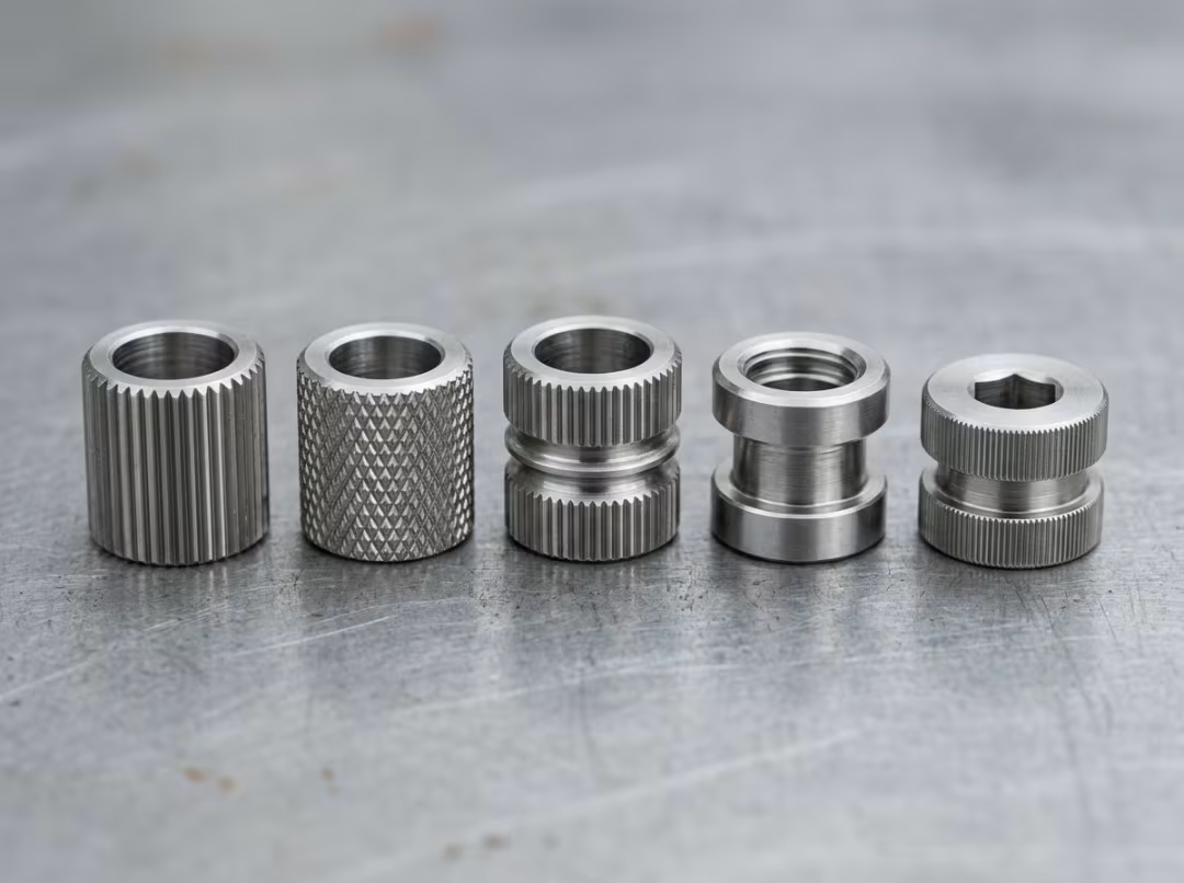
Retention features are what make the bond work. Knurls, undercuts, and grooves give the plastic geometry to lock into—as the plastic shrinks during cooling, it clamps onto those features, converting geometry into grip. A smooth insert gives the plastic nothing to grab. Straight knurls resist axial pull-out; diagonal or crossed knurls resist both pull-out and rotation. Match the pattern to the load the insert will actually see in service.
Sharp corners on the insert are a design error. Every sharp edge concentrates stress in the surrounding plastic and becomes a crack-initiation site—often not immediately, but after a few thermal cycles or months in the field. Radius the corners and you eliminate a predictable failure point.
Wall thickness around the insert needs to land in the right range. Too thin and you get cracking, sink marks, or weld lines where flow fronts converge behind the insert. Too thick and the section cools unevenly, inviting voids and longer cycle times. The goal is uniform, adequate plastic all the way around—enough to grip and carry load without working against itself during cooling.
Positioning is what prevents the first moment of failure. The insert must be positively located so that injection pressure can’t move it. When an insert shifts, surrounding walls go uneven, tolerances drift, and the lock weakens on the thin side. Solid locating features aren’t optional; they’re what holds the intended geometry together under real process conditions.
Matching the Plastic to the Insert
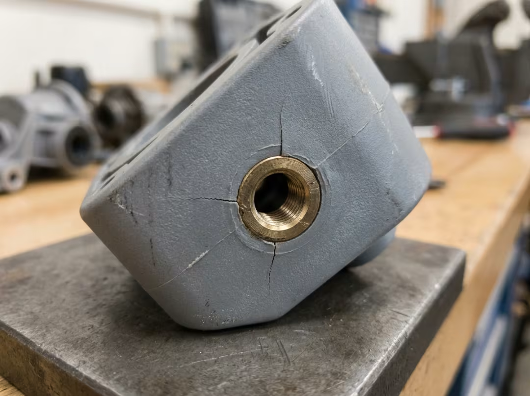
Thermal compatibility is the most important pairing decision and the one most likely to lead to delayed failures. Metal and plastic expand and contract at very different rates. A significant mismatch means the plastic builds internal stress as it cools and then cycles through temperature in service. That stress doesn’t announce itself on the production floor—it shows up weeks later as a crack radiating from the insert in a part that passed every quality check. This is the failure mode that quietly ruins production runs, and it traces directly back to a shrinkage mismatch that wasn’t evaluated at the design stage.
Resin selection sorts by application. Nylon and PBT are the workhorses—strong, dimensionally stable enough for most inserts, and forgiving to process. PP and ABS are used for lighter-duty, cost-sensitive parts where structural demands are modest. PEEK and other high-performance resins earn their cost premium only when the part faces sustained heat or aggressive chemical exposure that standard resins can’t survive—if you’re sourcing PEEK components, Essengold’s PEEK CNC machining and Nylon CNC machining services cover precision work in both materials.
Glass-filled grades add strength and creep resistance, which matters when the plastic has to hold thread torque or carry sustained load without relaxing over time. The trade-off is real: glass fill is harder on tooling, and filled resins behave differently around inserts than unfilled grades do—different shrinkage, different stiffness. You can’t drop a glass-filled resin into a design validated for an unfilled one without re-evaluating the fit and stress distribution.
Pick the plastic for actual operating conditions, not bench performance. A material that maintains tolerances at room temperature can fail under temperature fluctuations, chemical exposure, moisture absorption, or cyclic loading. Nylon absorbs moisture and changes dimensionally. Some resins soften at elevated temperatures; others go brittle in the cold. The service environment shapes the pairing decision as much as any mechanical property does.
Insert Materials and What They Buy You
Brass is the default for threaded inserts and electrical contacts—good conductivity, solid corrosion resistance, adequate thread strength for most applications. The majority of inserts in production hardware are brass.
Stainless and steel take over where higher strength or elevated-temperature service rules out brass.
Aluminum saves weight but is softer. Fine for non-structural features, but a poor choice for threads that will be torqued repeatedly—stripping and galling are real risks.
Plating adds corrosion resistance or improves surface finish where the base insert material needs protection in service.
Ultimately, bond strength, dimensional accuracy, and long-term durability all come down to the same two variables: insert geometry and material pairing. Get both right and the process delivers. Get either wrong and no adjustment to injection pressure or hold time fixes it.
How Strong Is the Bond, Really?
The bond is mechanical, not chemical. Plastic and metal don’t form meaningful chemical adhesion. What holds the assembly together is geometry—plastic flows under injection pressure into undercuts and around knurled surfaces, then shrinks and clamps as it cools. The more effective the retention features, the stronger the interlock.
This is why insert molding typically outperforms post-mold inserts on pull-out and push-out strength. In insert molding, the plastic is formed directly around the retention geometry under pressure. In press-fit or ultrasonic insertion, the plastic is pushed against or melted around the insert after the fact—less contact, less engagement, less strength.
A few things predictably weaken the bond: smooth inserts that give the plastic no geometry to grip; thin surrounding walls that crack under load or fail to develop full clamping force during cooling; weld lines behind the insert where flow fronts converge, creating a structural weak plane exactly where strength matters most; and shrinkage mismatch that builds residual stress over time.
With good knurling, adequate wall thickness, and a well-matched material pairing, a properly designed insert-molded part will typically outlast the demands of the application. But that result doesn’t happen by default—it’s a direct outcome of the design decisions above.
Cycle Time and Cost: When It Pays Off
Insert molding always runs a longer cycle than plain injection. Loading the insert—by hand or by robot—adds time that standard molding doesn’t carry. That’s a fixed cost. Better process settings don’t change it.
What changes the economics is what happens downstream. Robot loading cuts labor and produces repeatable cycle times suitable for high-volume production. More importantly, insert molding removes the assembly operation that would otherwise follow the molding step—no separate station, no extra handling, no labor fastening metal into finished plastic parts. Count the labor, floor space, and error risk that step represents, and the total delivered cost per part often drops even when the molding cycle is slower.
Tooling is more expensive and complex than standard injection tooling—the mold must locate and hold the insert through the full shot, and that precision costs money upfront.
The right way to evaluate the decision is total delivered cost per part, not cycle time or tooling cost in isolation. At volume, assembly savings and bond strength benefits accumulate across a long run and repay the tooling investment. At low volume, there aren’t enough parts to spread the tooling cost, and post-mold methods almost always win. The break-even is specific to each part and volume, so run the actual numbers before committing.
Where Insert Molding Is Used
Grouping by what the insert does is more useful than listing industries, because the same logic recurs across very different market segments.
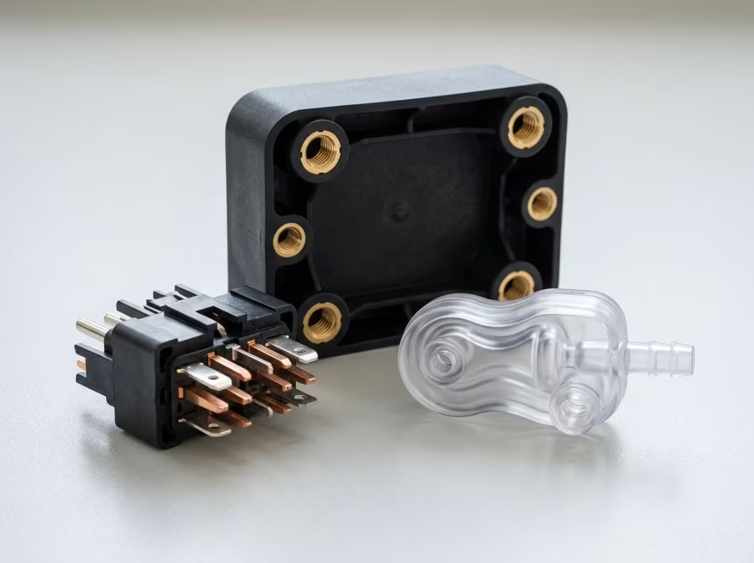
Threaded and structural. The largest category: brackets, housings, and panels with molded-in threaded inserts that give plastic a durable, reusable metal thread. These appear across automotive interiors, aerospace hardware, and industrial enclosures—anywhere a plastic assembly needs to be fastened and unfastened repeatedly without stripping.
Electrical. Inserts that carry current or make contact include connectors, battery terminals, charging contacts, and motor commutators. Molding the metal directly into the plastic locks in the electrical geometry and eliminates an assembly step, which matters in high-volume electronics and automotive production.
Medical. Molded-in metal hubs on surgical instruments, luer fittings combining a plastic body with a metal connection, device housings with sealed electrical feedthroughs. These parts demand tight tolerances and repeatable bond quality—both of which insert molding delivers when the design is done correctly.
The common thread: wherever a metal feature must reside within a plastic part for reliable strength and without a separate joining operation, insert molding is worth evaluating.
Frequently Asked Questions
What’s the difference between insert molding and overmolding?
Insert molding wraps plastic around a non-plastic preform—typically a metal insert, such as a threaded brass sleeve. Overmolding wraps plastic around a pre-molded plastic base, like a soft grip over a rigid handle. Quick rule: if the base is metal, it’s insert molding; if the base is plastic, it’s overmolding.
How strong is the bond between the insert and the plastic?
Strong—but the mechanism is mechanical interlock, not chemical adhesion. Plastic flows into knurls and undercuts under injection pressure, then shrinks and clamps as it cools. With proper retention geometry and well-matched materials, the bond typically holds well beyond the application’s load demands. Smooth inserts, thin surrounding walls, and shrinkage mismatch all compromise it.
Is insert molding cost-effective for low-volume production?
Usually not. Tooling is more complex and expensive than standard injection tooling, and at low volumes there aren’t enough parts to amortize that cost. Press-fit or ultrasonic inserts almost always make more financial sense for prototypes and small runs. Insert molding earns its economics at volume, where assembly savings repay the tooling investment.
What plastics work best with metal inserts?
Nylon and PBT cover most applications. PP and ABS handle cost-driven, lighter-duty parts. PEEK and other high-performance resins are worth it only when the application involves sustained heat or aggressive chemical exposure. Glass-filled grades add strength and creep resistance where the plastic needs to hold thread torque or carry sustained load over time.
How do you prevent the insert from shifting during injection?
Locate it positively in the mold using pins or seating features sized to resist injection pressure. If the insert can move, it will—and a shifted insert means uneven walls, lost tolerances, and a weaker bond on the thin side. Solid locating design is what keeps the geometry intact through the shot.
Conclusion
Insert molding combines a metal insert and plastic into one bonded part in a single cycle, trading a longer mold operation and more complex tooling for eliminated assembly and a stronger joint. That trade is the center of every decision around this process.
Durability comes down to insert geometry and material pairing. Get the retention features right and match the plastic to both the insert and the service environment, and you end up with a reliable, assembly-free component. Get either wrong, and no adjustment to molding parameters can recover it.
The best use of time before a design locks is a direct conversation with a molder about part geometry and production volume. That discussion surfaces tooling and design constraints early enough to act on—and confirms whether the part will actually perform in the field, rather than finding out after it ships. If you’re ready to move from design to production, Essengold’s CNC machining service handles precision metal and plastic work across a broad range of part types and volumes.