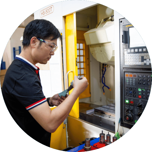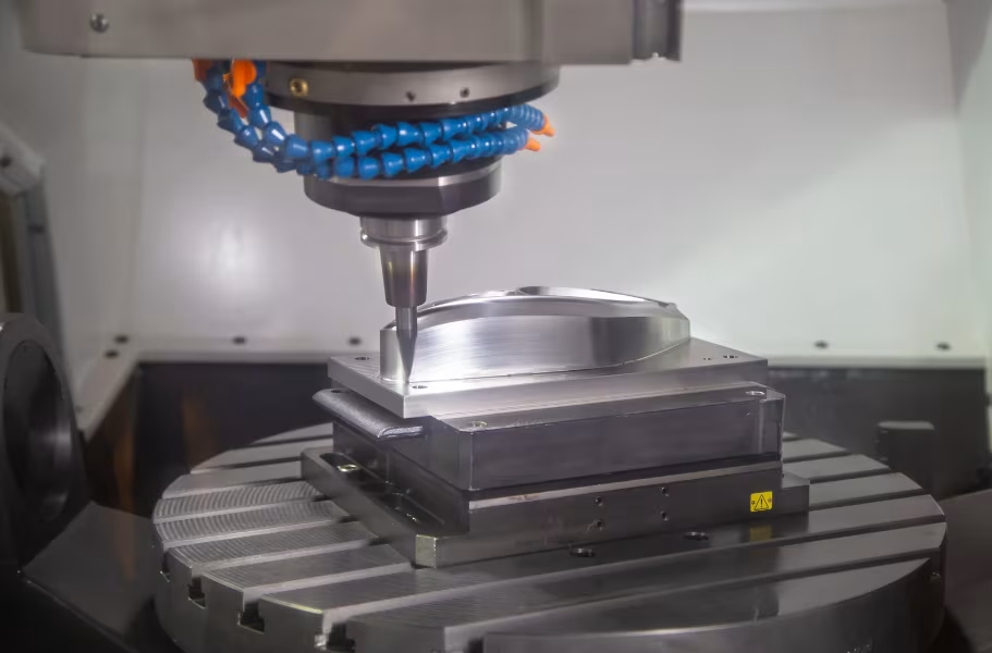
Take a solid block of 6061 aluminum. A few hours later, it has thin walls, lightening pockets, threaded mounting holes, and sealing faces that align within a few thousandths of an inch. No mold was built. No casting was poured. A rotating cutter followed a programmed path and removed everything that wasn’t the part. That’s CNC milling — and it produces more precise metal and plastic parts than any other machining process.
This guide walks through how milling works from the shop floor up. You’ll understand what happens between uploading a CAD file and receiving a finished part, which operations and machine configurations suit which features, what drives cost and lead time, and where milling genuinely outperforms the alternatives — and where it doesn’t.
What Is CNC Milling?
CNC milling is a subtractive manufacturing process where a rotating multi-point cutting tool removes material from a fixed workpiece to produce a programmed shape. CNC stands for computer numerical control. A computer converts digital instructions into precise machine movements, so the cutter follows the same path on part one and part five hundred.
Milling sits within the broader family of CNC machining, but it has a defining characteristic: the cutter spins, not the workpiece. The workpiece is clamped to a table while the tool moves against it. That’s the opposite of CNC turning, where the workpiece rotates, and a stationary tool shapes it. That single difference determines which process fits which part. Turning excels at round, symmetrical parts — shafts, bushings, bolts. Milling handles flat faces, pockets, slots, angled features, and freeform 3D surfaces, which describes most brackets, housings, and enclosures in modern products.
Key Components of a CNC Milling Machine
Five parts of the machine do the core work:
- Spindle: Holds and rotates the cutting tool, typically at 8,000–20,000+ RPM on modern machining centers.
- Cutting tool: End mills, face mills, drills, taps. Each has a geometry designed for a specific feature or material.
- Worktable and axes: Move the part or spindle along X, Y, and Z — plus rotary axes on 4- and 5-axis machines.
- CNC controller: Reads the program and coordinates every axis movement, spindle speed, and coolant command.
- Workholding: Vises, fixtures, and clamps that lock the part rigidly in position. Getting this right often matters more than the toolpath itself.
How Does CNC Milling Work? The Step-by-Step Process
Every milled part goes through five stages. Problems at any stage show up later as cost overruns, delays, or scrapped parts.
1. Design the part in CAD. The engineer builds a 3D model and — ideally — a 2D drawing that flags critical tolerances, threads, and surface finishes. The model defines the shape. The drawing tells the shop what actually matters. A model delivered without a drawing puts the machinist in the position of guessing which dimensions are critical, and that guess is rarely cheap.
2. Program toolpaths in CAM. A programmer selects tools, sets speeds and feed rates, and sequences the cuts. The software outputs G-code — the coordinate-based instructions the controller reads line by line. Good programming isn’t just about getting the shape right. It balances material removal rates against tool life and dimensional accuracy.
3. Set up the machine. The operator mounts the workholding, loads the tools, measures tool lengths, and establishes the work zero — the reference point from which every move is measured. This stage is underestimated. A thin-walled part that vibrates in a poorly chosen vise will never hold its tolerances, regardless of how clean the program is. Fixturing is where experienced shops earn their money.
4. Machine the part. Roughing passes remove the bulk of the material quickly, leaving a small amount of stock. Finishing passes then take light cuts to hit final dimensions and surface finish. Coolant flushes chips out of the cut and keeps temperatures down — thermal growth from heat is a real source of dimensional error on tight-tolerance work.
5. Inspect and finish. Parts are measured with calipers, micrometers, or a CMM for complex geometry. Edges are deburred. Then surface finishing is applied — anodizing, bead blasting, plating, or whatever the drawing specifies. Skipping or rushing this stage means you’re trusting the machine rather than verifying the part.
Types of CNC Milling Operations and Machines
What a milling machine can produce depends on two factors: the operations it runs and the number of axes it can move across simultaneously.
Common CNC Milling Operations
Most parts require a combination of several operations within a single program:
- Face milling: A large-diameter cutter flattens the top surface. Usually the first cut, used to establish a clean reference face.
- Peripheral (slab) milling: The side of the cutter works wide surfaces and outer edges — the walls of a housing, for example.
- Pocket and slot milling: Clears enclosed cavities and channels, such as electronics compartments, O-ring grooves, and keyways.
- Contour and profile milling: Traces outer shapes and 3D sculpted surfaces — ergonomic grips, turbine blade profiles, complex organic geometry.
- Drilling and tapping: Holes and threads produced in the same setup stay accurately positioned relative to other features.
3-Axis vs. 4-Axis vs. 5-Axis Milling
|
Configuration |
Best For |
Trade-off |
|---|---|---|
|
3-axis |
Flat parts, pockets, features reachable from the top |
Multiple setups needed for features on other faces |
|
4-axis |
Features around a cylinder, cam profiles, multi-sided parts |
Moderate added cost; one rotary axis only |
|
5-axis |
Impellers, undercuts, compound angles, organic shapes |
Higher machine rate and programming complexity |
Every time a part is unclamped and re-fixtured, small positional errors accumulate. A 5-axis machine can reach the undercut blades of an impeller in one setup instead of three, improving feature-to-feature accuracy and cutting handling time significantly. That said, 5-axis isn’t the right answer for every job. A simple plate with pockets is faster and cheaper on a 3-axis machine. Vertical mills suit most prototype and low-volume work. Horizontal mills clear chips more efficiently and often use pallet changers, making them well-suited to production runs. Our CNC milling service covers all three configurations.
What Materials Can Be CNC Milled?
Almost any rigid metal or engineering plastic can be milled. That said, material choice directly affects cycle time, tool wear, achievable tolerances, and cost per part.
Metals
|
Material |
Why Choose It |
|---|---|
|
Excellent machinability, low cost, solid all-round strength |
|
|
Aluminum 7075 |
Near-steel strength at roughly a third of the weight |
|
Corrosion resistance; 303 is the most machinable grade |
|
|
High strength-to-weight ratio, biocompatible; slow and costly to cut |
|
|
Machines fast and clean; reliable for fittings and connectors |
|
|
Superior electrical and thermal conductivity for busbars and heat sinks |
For a full look at our metal capabilities, visit our CNC metal machining service page.
Plastics
|
Material |
Why Choose It |
|---|---|
|
Stiff, low-friction, holds tight tolerances consistently |
|
|
Inexpensive and tough; a go-to for prototype housings |
|
|
Wear-resistant and impact-resistant for gears and bushings |
|
|
High heat and chemical resistance; used in medical and aerospace |
|
|
Optically clear for lenses, covers, and light guides |
We also offer CNC plastic machining across a wider range of engineering-grade materials.
Harder, more abrasive materials add cost through slower feed rates and faster tool wear. Plastics present a different set of challenges — they expand with heat and deflect under cutting forces, so very tight tolerances on large plastic parts require careful process control, not just slower speeds.
Applications of CNC Milling Across Industries
Milling shows up wherever parts need precision geometry, reliable material properties, and fast turnaround:
- Aerospace: Structural brackets and avionics housings, typically in 7075 aluminum or titanium, where both weight and fatigue life matter.
- Automotive and EV: Battery enclosure prototypes, motor housings, and engine components that need validation before tooling is committed.
- Medical: Surgical instrument parts and diagnostic device housings in stainless steel, titanium, or PEEK, often with strict traceability requirements.
- Electronics: Heat sinks with tight fin spacing and machined aluminum enclosures that double as EMI shielding.
- Robotics and automation: End-effectors, sensor mounts, and precision mounting plates that evolve through multiple design revisions.
- Product development: Functional prototypes in production-grade materials, so engineers test real performance rather than a 3D-printed stand-in.
CNC Milling Tolerances and Surface Finish
Understanding what tolerances and finishes are achievable — and what they cost — prevents over-specifying parts and blowing the budget on features that don’t affect function.
Standard vs. tight tolerances
For most machined features, ±0.005 in. (±0.13 mm) is a practical standard tolerance that most shops can hold reliably without special setups. When a sealing face, bearing bore, or precision fit genuinely requires it, ±0.001 in. (±0.025 mm) or tighter is achievable — but it adds setup time, requires slower finishing passes, and demands CMM verification rather than a quick caliper check. The rule is simple: apply tight tolerances only where the part’s function actually demands it. A housing wall with no mating surface doesn’t need a ±0.001 in. callout, and specifying one unnecessarily increases cost and lead time with no engineering gain.
As-machined surface finish
A standard milled surface typically comes in around Ra 1.6–3.2 µm (63–125 µin). That’s acceptable for most structural and non-sealing surfaces. If a surface needs to seal against a gasket, seat a bearing, or look clean for a customer-facing product, it may need a finer pass or a secondary finishing operation.
Common surface finishes for milled parts
Essengold offers a full range of CNC machining surface finishes, including:
- Anodizing (Type II and Type III): Corrosion resistance and color options for aluminum parts. Type III (hard anodizing) adds surface hardness.
- Bead blasting: Creates a uniform matte texture that removes tool marks. Often used before anodizing.
- Electropolishing: Smooths stainless steel at a micro level, improving corrosion resistance and cleanability.
- Plating (nickel, chrome, zinc): Adds wear resistance or conductivity depending on the application.
- Powder coating: Durable color finish for external-facing aluminum or steel parts.
Specify the finish on the drawing, not just verbally. A supplier who sees “anodize” without a type or color will make assumptions that may not match your design intent.
CNC Milling Design Guidelines for Better Parts
Most avoidable cost comes from features that are hard to machine, not from material or quantity. These guidelines apply to nearly every milled part:
Internal corner radii
Round cutters can’t produce a perfectly sharp inside corner. If your design has a sharp internal corner, the machinist must either slow down and bury the cutter into the corner (increasing cycle time and tool wear) or leave the feature undersized and send it to EDM. The fix is simple: add a radius to every internal corner, slightly larger than the cutter radius. Even a 0.5 mm radius makes a difference. If a sharp corner is structurally necessary, design in a relief groove instead.
Pocket depth
A practical rule is to keep pocket depth at no more than 3–4× the cutter diameter. Deeper pockets need longer tools with more flex, which causes chatter, reduces accuracy, and forces slower speeds. If your design requires a deep, narrow pocket, talk to the shop before you finalize the model. Sometimes the solution is a two-step approach — rough from one side, finish from another — but it’s better to know that before the quote comes back.
Wall thickness
Thin walls deflect under cutting forces and vibrate, which degrades surface finish and accuracy. As a general starting point, keep walls at least 0.8 mm thick for aluminum and 1.5 mm for steel. This isn’t a hard rule — experienced shops can mill thinner — but going below these figures usually requires slower speeds, more passes, and careful fixturing.
Tolerances and GD&T
Call out tight tolerances only on features where fit, function, or assembly requires it. If you’re not sure, ask the shop. A good supplier will tell you which features actually drive the machining cost and whether the tolerance adds real value. Using GD&T correctly — controlling position, flatness, and runout where they matter — is more effective than adding ±0.001 in. everywhere.
Hole depth and thread engagement
Deep holes relative to diameter require long drill bits that can walk, deflect, or break. Standard drill depth is around 3× the hole diameter. Threads should have enough engagement—typically 1.5–2× the fastener diameter in aluminum, slightly less in steel—but deep blind-tapped holes in hard materials are a common source of broken taps and scrapped parts.
Design for the number of setups
Every time the part has to be re-fixtured, there’s a chance for small positional errors. If your part has features on five faces that all need to be precisely positioned relative to each other, consider whether a 5-axis approach makes sense, or whether the design can be simplified to fewer setups. Talk to the shop before the design is locked.
What Affects CNC Milling Cost and Lead Time?
Milling costs are not arbitrary. Understanding the levers helps you make better decisions at the design stage.
Material
Aluminum is the least expensive to machine. Titanium and PEEK are among the most expensive — not just because the raw material costs more, but because they require slower speeds, more tool changes, and more careful handling. Stainless steel falls in between. If you’re prototyping a part that will eventually go to titanium, consider starting in aluminum 7075 to validate the design first.
Geometry complexity
More operations, more setups, and harder-to-reach features all add time. A simple bracket with pockets and a few holes is fast. A part with features on four faces, undercuts, and tight-tolerance bores takes longer at every stage — programming, setup, machining, and inspection.
Tolerance requirements
Standard tolerances run fast. Tight tolerances need slower finishing passes, more careful tool selection, temperature-controlled environments in some cases, and CMM inspection instead of hand gauging. Every time you add a ±0.001 in. callout, you’re adding machine time and inspection time.
Quantity
Setup time is fixed. If you’re making one part, all the setup cost sits on that one part. At 50 or 100 pieces, it spreads across the run, and cost per part drops significantly. For very high volumes, consider whether the design is more cost-effective in a cast or molded form with milled secondary features.
Surface finish
An as-machined part is the fastest and cheapest option. Each additional finishing step — bead blast, anodize, plate — adds time and cost. Stack multiple finishes and lead time can grow by several days.
Setup count
Fewer setups mean lower cost and better accuracy. A part that can be fully machined in one or two clampings is significantly cheaper than one that needs four or five repositions to reach all its features.
Common CNC Milling Challenges and How Experienced Shops Solve Them
Milling is reliable, but it’s not without problems. Knowing what goes wrong — and how good shops prevent it — helps you assess whether a supplier actually knows what they’re doing.
Chatter
Chatter is vibration between the tool and workpiece that leaves a wavy surface pattern and can break tools or blow tolerances. It’s caused by tool overhang, poor fixturing, incorrect speeds, or a combination of all three. The fix usually involves shortening the tool reach, changing the spindle speed to avoid a resonant frequency, or improving workholding. Shops that have seen the problem before will adjust parameters immediately rather than running a full batch of bad parts.
Thin-wall distortion
When milling thin-walled features — the walls of an aluminum housing, for example — the material can flex under cutting forces and spring back, leaving the wall out of tolerance. Experienced machinists alternate sides during cutting, leaving thin features supported until the final passes. Some use low-force finishing strategies specifically designed for thin-wall work.
Heat buildup in hard materials
Titanium and stainless steel generate significant heat during cutting. That heat expands the workpiece and shifts the finished dimensions once the part cools. Shops that run these materials routinely use flood coolant, slow down at critical features, and measure parts after they’ve had time to stabilize. Shops that don’t will sometimes deliver parts that are in spec when hot and out of spec on the CMM the next morning.
Tool deflection on deep features
Long tools flex under side loads. The deeper a pocket or the longer the tool reach, the more the tip deflects from the programmed path. This shows up as tapered walls or features that are on-size at the top but oversized at the bottom. Skilled programmers compensate by using climb milling on finishing passes, reducing radial depth, and sometimes using roughing and finishing tools of different lengths.
Burrs
Every machined edge produces some form of burr. On holes and pockets, they can interfere with mating parts and present injury risk. Deburring is part of every professional milling job, but the thoroughness varies. Specify on the drawing whether edges need to be broken, chamfered, or just hand-deburred, especially for any surface that contacts a sealing element, bearing, or mating part.
CNC Milling vs. Other Manufacturing Methods
The right process depends on part geometry, material, and production volume:
|
Method |
Best For |
Choose Milling When… |
|---|---|---|
|
Round, symmetrical parts |
The part has flat faces, pockets, or off-axis features |
|
|
3D printing |
Internal channels, lattices, fast concept models |
You need production-grade material properties and tight tolerances |
|
Injection molding |
Plastic parts at 5,000+ units |
Volumes are low, or the design is still in flux |
|
Casting |
Large metal parts at high volume |
You need precision secondary features or can’t wait for tooling |
Many parts combine processes. A cast housing, for example, often gets its sealing faces, bores, and threaded inserts milled as a secondary operation. For hybrid requirements, our contract machining and custom metal fabrication capabilities work together.
How to Choose the Right CNC Milling Supplier
The difference between a shop that machines your files and one that actually engineers your parts shows up in the quote, the first article, and what happens when something goes wrong.
Axis capability
Check whether they have 3-, 4-, and 5-axis machines in-house, or whether they sub out complex work. If your part has undercuts or compound angles, you want a shop that owns the right machine and programs it regularly.
In-house inspection
Ask whether they have a CMM and whether inspection reports are standard or optional. Shops that inspect every job catch problems before shipment. Shops that rely on operator checks alone miss more. Our inspection and shipping process includes CMM verification and documentation for every project.
DFM review before the quote
A supplier that sends back a quote without any design feedback is processing orders, not solving problems. A good shop will flag internal corners that need a radius, pockets that are too deep for a standard tool, or tolerance callouts that add cost without adding function. That conversation before machining starts is worth more than a slightly lower unit price.
Material and finish experience
Running aluminum is not the same as running titanium or PEEK. Ask specifically about their experience with your material — tooling strategy, coolant approach, typical tolerances achieved. A supplier who runs those materials routinely will have a process that’s already dialed in.
Prototype-to-production continuity
If you’re starting with prototypes but expect to scale, choose a shop that can handle both. Switching suppliers between prototype and production means requalifying the process, re-fixturing the part, and accepting that the second supplier will have a learning curve. Working with one shop through both stages avoids that.
Communication and lead time transparency
Lead time commitments matter less than communication when something changes. A shop that tells you on day one that they found a problem is a better partner than one that ships late and explains afterward.
Frequently Asked Questions
What is the difference between CNC milling and CNC machining?
CNC machining is the broader category that includes milling, turning, drilling, grinding, and other processes. CNC milling specifically uses a rotating multi-point cutter to remove material from a fixed workpiece. When people say “CNC machined part,” they often mean a milled part, because milling is the most common process for producing complex prismatic geometry.
What tolerances can CNC milling achieve?
Standard milling tolerances are typically ±0.005 in. (±0.13 mm). With proper setup, tooling, and finishing passes, ±0.001 in. (±0.025 mm) is achievable on critical features. Tighter tolerances are possible in controlled environments with specialized tooling, but they add cost at every stage.
Is CNC milling good for prototypes?
Yes — it’s one of the best options for functional prototypes. There’s no tooling to pay for, the process runs in production-grade materials, and lead times are typically measured in days rather than weeks. If your design is likely to change, milling is forgiving: you update the CAD file, regenerate the toolpath, and machine a revised part without throwing away expensive tooling.
When should I choose milling over turning?
Choose milling when your part has features that aren’t rotationally symmetric — flat faces, pockets, slots, angled surfaces, or off-center holes. Choose turning when the part is primarily cylindrical. Many parts combine both: a turned shaft with a milled keyway, for example, or a turned housing with milled mounting faces. For those situations, millturn machining handles both in a single setup.
What is the most commonly milled material?
Aluminum — specifically 6061 — is by far the most commonly milled material. It machines fast, holds good tolerances, is available in almost any stock form, and suits a wide range of applications. 7075 is the go-to when strength requirements push beyond what 6061 can offer.
Can CNC milling produce threads?
Yes. Tapping and thread milling are standard operations done on most CNC milling machines. Tapping is faster and simpler for common thread sizes. Thread milling is preferred for large diameters, blind holes in hard materials, or when thread quality and position tolerance are critical.
Ready to Start Your CNC Milling Project?
CNC milling is one of the most capable and flexible ways to turn a digital model into a precise, functional part — especially when your design is complex, your material matters, or the program is still evolving between iterations.
At Essengold, we run CNC milling across 3-, 4-, and 5-axis platforms, in metals and engineering plastics, from single prototypes through to production volumes. Every project includes a DFM review before we cut and an in-house CMM inspection before parts ship. If your part needs secondary operations — finishing, welding, or assembly — our contract machining team handles the full workflow under one roof.
Upload your CAD file to get a quote and practical feedback on how to make your part better, faster, and more cost-effective.