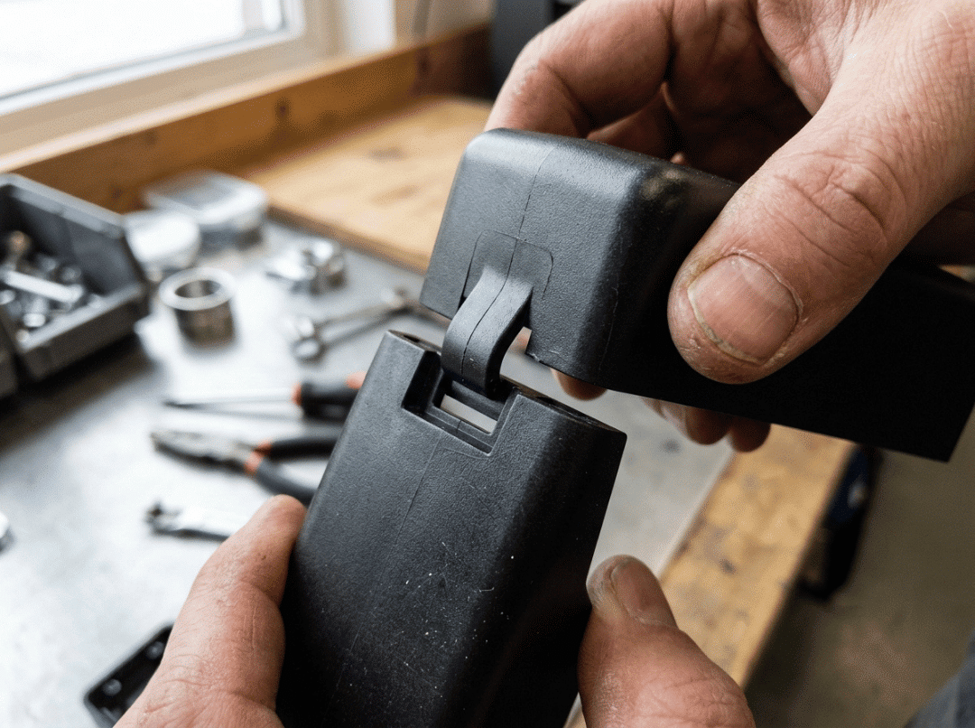
Snap fits fail in predictable ways. The arm shears on the first assembly run. The prototype holds for weeks, then the production joint loosens in service. The CAD looks fine, the drawing passes review, and the first batch comes back with cracked hooks.
None of that is bad luck. Nearly every snap fit failure traces to one of three upstream decisions: geometry that pushes the arm past its strain limit, a material chosen for stiffness rather than the duty cycle, or a design that ignores how the part will actually be manufactured.
This guide is about those decisions. The weight sits on cantilever design — the type that covers the large majority of real applications and where small geometry mistakes carry the highest cost. Material selection, failure analysis, and process differences for injection molding versus 3D printing are each treated as separate topics because they each demand different thinking.
What Makes a Snap Fit Succeed or Fail
Understanding why snap fits break is more useful than any formula. The pattern is consistent across materials, industries, and part sizes.
The five root causes behind most failures
1. Root strain exceeds the material’s allowable limit.
This is the most common cause by a wide margin. The arm deflects further than the material tolerates and either cracks immediately or takes a permanent set that kills retention.
2. A sharp corner at the root concentrates stress.
An arm correctly sized for strain can still shear off if the base has a square inside corner. That corner acts as a stress riser, driving local strain well above what beam equations predict. The fix costs nothing in CAD and is almost always overlooked.
3. Material chosen for stiffness, not creep or fatigue.
A stiff plastic feels like a firm, confident snap. It may also relax under sustained load or crack after a few hundred cycles. Stiffness and durability are not the same thing.
4. Retention force set too high.
A joint tuned for maximum hold often forces the arm past a safe strain limit every time it opens. That trades a secure latch for a short service life.
5. Process mismatch.
A part designed for injection molding, then printed for a “quick check,” behaves differently in both geometry and material. Passing the prototype test proves very little about the production part.
The tradeoff that governs every design decision
Every snap fit sits between two opposing requirements: insertion force must be low enough for clean assembly, and retention force must be high enough to keep the joint seated.
A shallow lead angle makes the arm slide in easily — and also makes it easier to pop back out. A steep return angle holds the joint firmly but demands more deflection to release, which raises strain on every cycle. Good snap fit design finds the point where assembly is manageable and retention is reliable, without ever pushing strain past the limit.
That framing carries through everything that follows: snap fit design is a strain-management problem first, and a geometry problem second.
What Is a Snap Fit Joint?
A snap fit is an interlocking feature that joins two parts through elastic deflection. One part carries a flexible hook, bead, or ridge that deflects during assembly and springs back to lock into a recess on the mating part. No separate fastener is involved.
Permanent versus releasable joints
The return angle of the hook determines whether the joint comes apart again.
- A shallow return angle allows separation under a defined pull force — right for battery covers, service panels, or anything the user expects to open.
- A steep or square return angle locks the joint permanently. Releasing it means deliberately deflecting the arm with a tool, or the joint does not release without damage — right for sealed enclosures that should never be opened in normal use.
Decide this in the first design iteration. A joint intended for occasional release and later expected to survive hundreds of cycles needs a different geometry and a different material than a one-time assembly.
The Three Snap Fit Types — Which One Fits Your Part
Listing types without explaining when to use each one is not particularly useful. The question is not “what exists” but “which one fits this part.”
Cantilever snap fit
A fixed beam with a hook at the free end. The beam bends during assembly and springs back to latch.
Where it works: housings, enclosures, brackets, panel clips — the large majority of plastic product assemblies.
Why it is the default: straightforward to calculate, easy to mold or print, and predictable in how it behaves.
Where it breaks down: spaces too confined for useful arm length, or circular parts where an annular design is geometrically more natural. When a straight arm is too long for the envelope, a U- or L-shaped arm folds a longer effective beam into the available space.
Annular snap fit
A continuous ridge around a circular or elliptical part that seats into a matching groove. Common in pen caps, bottle lids, and cylindrical housings.
Where it works: round or oval assemblies where a full-perimeter grip is needed.
Design challenge: the ridge must expand over the mating diameter during assembly, creating multiaxial hoop stress rather than simple bending. Harder to estimate than a cantilever, and demands more careful strain analysis. Lead and return angles on the ridge control permanence, following the same logic as a cantilever hook.
Torsion snap fit
Deflection energy is stored by twisting a bar, not bending a beam. Pressing one end of a rocker arm twists the torsion bar and lifts the catch at the other end.
Where it works: latches, doors, and lids that open repeatedly.
What controls the force: the length and diameter of the torsion bar, not the rocker arm geometry. Longer or thinner bar releases more easily; shorter or thicker holds harder.
Selection reference
|
Type |
Best application |
Release |
Calculation |
|---|---|---|---|
|
Cantilever |
Housings, brackets, panel clips |
Permanent or releasable (hook angle) |
Low |
|
Annular |
Caps, lids, cylindrical assemblies |
Permanent or releasable (ridge angle) |
High |
|
Torsion |
Repeated-release latches and doors |
Releasable by design |
Moderate |
A practical shortcut: flat or bracket-like part with occasional release → cantilever. Round sealing part → annular. Frequently opened latch → torsion.
Cantilever Snap Fit Design: The Rules That Determine Whether It Holds
This section carries the most weight in the guide because cantilever geometry is where most snap fit failures originate and where small decisions have the largest downstream effect. Every rule below serves one objective: keep root strain inside the material’s limit while delivering the retention the application requires.
Arm length — why longer usually means safer
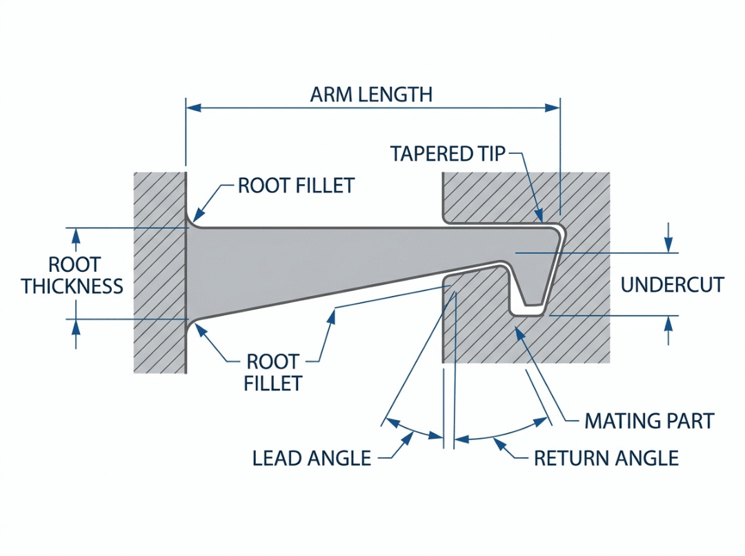
A longer arm is often assumed to be weaker. For strain, the opposite is usually true. The same snap depth spread over a longer beam produces less peak strain at the root, because the deflection is distributed over more material. Lengthening the arm reduces root strain — which is what prevents cracking.
The tradeoff is physical space and, to a smaller degree, assembly feel. When a straight arm will not fit, route a U- or L-shaped path through the available envelope to achieve the necessary effective length.
This rule has a practical boundary. An arm that is too long and thin may buckle sideways or feel uncomfortably soft. Between too short and slightly too long, the longer option is the safer design error.
Root thickness and the tapered arm
A constant-thickness arm concentrates nearly all its strain at the root, where the bending moment is highest. The tip contributes almost nothing while the base carries nearly everything.
Tapering the arm — thicker at the root, thinner toward the tip — distributes strain more evenly. A common starting point is a tip thickness around half the root thickness. The result: either lower peak root strain for the same undercut depth, or a deeper usable snap for the same peak strain.
Root fillet — the highest-impact single change
If you make one modification to a struggling snap fit, fillet the root. A square inside corner at the base is a stress riser that drives local strain well above what beam equations show. It is the most common reason arms shear on first assembly, and it costs almost nothing to fix in CAD.
A practical minimum: root fillet radius ≥ 0.5× the base arm thickness. Larger is generally better — up to the point where the fillet stiffens the arm enough to reduce usable deflection. Below that ratio, the corner produces cracking that better geometry elsewhere cannot prevent.
Undercut — size it from strain, not intuition
The undercut is how far the hook overlaps the mating lip, and also the deflection the arm must complete during every assembly. The two are directly linked.
The correct approach: start from the material’s allowable strain, work back through arm geometry to find the maximum safe deflection, and let that set the undercut depth. Picking a snap depth first and checking strain afterward is how parts end up over-strained by design.
Lead and return angles — controlling insertion and hold
Two angles govern the joint’s behavior:
- Lead angle (the entry ramp): lower values make insertion easier. Most designs fall between 25° and 35°.
- Return angle (the locking face): a shallow angle allows release under load; a steep angle near 90° locks the joint permanently or requires deliberate tool release.
The lead angle tunes how the assembly feels going together. The return angle determines how firmly it stays — and whether it stays at all under sustained load.
Insertion force versus retention force — tuning the balance
To reduce insertion effort without sacrificing hold: lower the lead angle and lengthen or taper the arm while keeping the return angle steep. This keeps assembly comfortable without compromising retention. Calculated deflection force gives a baseline; add a friction factor of 0.2 to 0.5 for plastic-on-plastic contact to get closer to the real assembly effort.
Allowable strain — the number that governs everything
For snap arms, the design limit is strain, not stress. The arm deflects and recovers, and the question is always whether the material can sustain that deflection without damage — once, or repeatedly.
- One-time assembly: higher allowable strain is acceptable because the arm reaches full deflection only once.
- Repeated assembly: design well below the published limit. Fatigue accumulates with every cycle, and a joint that survives the first hundred openings may fail at the thousandth.
With root strain inside the material’s allowable value and the corner properly filleted, most cantilever failures do not happen.
Snap Fit Material Selection — What Actually Matters
Material choice determines whether a snap fit holds for its design life or loosens in service within weeks. Stiffness gets the most attention; for snap fits, it is rarely the property that matters most.
The properties that decide performance
- Flexural modulus: stiffness — how much force to deflect the arm. Higher gives a firmer snap and higher insertion force, but does not predict long-term retention.
- Allowable strain: how far the arm can safely deflect. This sets the practical undercut limit. A high-modulus material with low allowable strain produces a stiff arm that cannot flex enough to be useful.
- Creep resistance: whether the joint maintains retention under sustained load over months or years. This is what causes joints to “loosen over time.”
- Fatigue resistance: whether the arm survives repeated open-close cycles without cracking.
- Toughness: resistance to brittle fracture at the root, particularly under impact or low-temperature conditions.
A material can be stiff and still be a poor snap fit choice if it creeps under standing load or fatigues in repeated use.
Material-by-material guidance
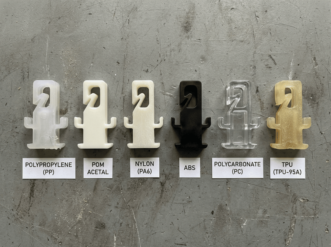
PP (polypropylene): the strongest flex-fatigue resistance of any common snap fit plastic — the same property that makes it the standard for living hinges. Low modulus and forgiving of repeated deflection. The default choice for any joint that opens regularly.
POM / acetal: high stiffness and reliable fatigue resistance, well matched to durable latches and precise catches. Creep under sustained standing load is worth monitoring. Less forgiving of sharp corners than softer resins — a proper root fillet is especially important here.
PA / nylon: strong and tough, but moisture uptake changes both stiffness and dimensions between dry-as-molded and in-service states. Design to the conditioned, in-service state. Ignoring moisture shift is one of the more common reasons nylon snap fits behave unexpectedly in the field.
ABS: easy to mold, dimensionally stable, and a practical general-purpose choice. Moderate strain and fatigue limits — reliable for one-time assemblies and low-cycle applications, less suited to anything that opens frequently.
PC (polycarbonate): strong and tough with higher stiffness. More prone to stress whitening at high-strain corners than most other engineering plastics, which makes a generous root fillet more important here than almost anywhere else.
TPU / TPE: very high flexibility and allowable strain. Right for high-deflection snaps or soft-latch applications where a rigid arm would crack. Low modulus means a gentle, compliant hold rather than a firm latch feel.
Comparison at a glance
|
Material |
Stiffness |
Allowable strain |
Creep resistance |
Fatigue resistance |
Common use |
|---|---|---|---|---|---|
|
PP |
Low |
High |
Moderate |
Excellent |
Reusable clips, living hinges |
|
POM / acetal |
High |
Moderate |
Moderate |
Good |
Durable latches, precise catches |
|
PA / nylon |
Moderate–high |
Moderate |
Good |
Good |
Structural clips (account for moisture) |
|
ABS |
Moderate |
Moderate |
Moderate |
Moderate |
General enclosures, low-cycle snaps |
|
PC |
High |
Moderate |
Good |
Moderate |
Tough housings (fillet the root) |
|
TPU / TPE |
Very low |
Very high |
Low |
Good |
Soft latches, high-deflection snaps |
Treat these as directional. Grade, fillers, and service temperature shift every value. Confirm against the specific resin’s datasheet before finalizing a design.
One-time versus repeated use: the duty cycle changes everything
- Repeated use (service covers, reusable latches): prioritize fatigue resistance and low creep. PP and POM are the most proven picks.
- One-time assembly (sealed enclosures, permanent locks): a higher allowable strain is acceptable because the arm fully deflects only once. This makes stiffer materials practical that would fail quickly under repeated cycling.
This distinction changes the material decision more than most designers expect. Getting it backward — choosing a stiff, creep-resistant material for a joint that opens daily — is one of the more common and avoidable mismatches.
Snap Fit Formulas — What They’re Telling You to Change
Equations for snap fits are most useful when you understand what each variable controls, not just how to substitute numbers. The goal is knowing which dimension to adjust and in which direction.
The variables
- l — arm length: longer reduces strain for a given deflection.
- h — thickness at the root: thinner reduces strain but softens both insertion feel and retention.
- b — width at the root: wider increases stiffness and deflection force without significantly affecting strain.
- y — deflection depth (the undercut): how far the arm travels during assembly.
- ε — allowable strain: the material’s ceiling. Everything else must stay under this number.
- E — flexural modulus: the material’s stiffness, which governs force.
Maximum strain at the root
For a straight cantilever with uniform cross-section:
ε = (3 × h × y) / (2 × l²)
What this shows: strain rises with root thickness and undercut depth, and falls sharply with arm length — because length is squared. That is the quantitative basis for the design rules above. If calculated strain exceeds the material’s allowable value, the adjustments are direct: lengthen the arm, reduce the root thickness, or reduce the undercut.
Deflection force and assembly force
Force to deflect the arm:
F = (b × h² × E × ε) / (6 × l)
Actual assembly force is higher due to friction on the lead surface:
F(mating) = F × (1 + friction factor)
For plastic on plastic, a friction factor between 0.2 and 0.5 is a reasonable range depending on material pairing and surface finish.
Worked example: a POM cantilever clip
|
Parameter |
Value |
|---|---|
|
Arm length (l) |
20 mm |
|
Root thickness (h) |
2 mm |
|
Width (b) |
5 mm |
|
Required undercut (y) |
1.2 mm |
|
Allowable strain (ε) |
0.06 (6%, one-time value for acetal) |
|
Flexural modulus (E) |
2,600 MPa |
Strain check:
ε = (3 × 2 × 1.2) / (2 × 400) = 7.2 / 800 = 0.009 (0.9%)
Well under the 6% ceiling. There is considerable headroom — the undercut could be deepened or the arm shortened if space is constrained, without approaching the limit.
Deflection force:
F = (5 × 4 × 2,600 × 0.009) / 120 = 3.9 N
Assembly force at friction factor 0.3:
F(mating) = 3.9 × 1.3 = 5.1 N
Reading the result: approximately 5 N to assemble, with root strain at 0.9% against a 6% limit. If insertion felt too firm, thinning the root or lengthening the arm reduces it directly. If the hold felt too light, the undercut has room to grow — strain has headroom to absorb it.
Where the formula stops
These equations assume a straight arm with constant cross-section and sharp corners. A tapered arm, a root fillet, and a 3D-printed part with direction-dependent strength all shift the result away from this baseline. Use the formula to confirm you are in a safe zone and to compare options quickly. For structurally critical applications, follow it with FEA and a physical prototype. The formula tells you whether the design is plausible; the prototype tells you whether it actually works.
Common Snap Fit Failures — Causes and What to Do About Them
Most snap fit failures fit one of the patterns below. Each has a design fix and, where relevant, a manufacturing fix. The design fix is almost always cheaper.
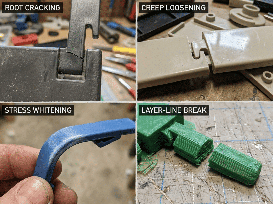
|
Failure |
Cause |
Design fix |
Manufacturing fix |
|---|---|---|---|
|
Root cracking on first assembly |
Over-strain combined with a sharp inside corner |
Root fillet ≥ 0.5× base thickness; lengthen or taper the arm |
Check for sink or notch at the root post-molding |
|
Joint loosens over time |
Creep under sustained standing load |
Redesign so the latched joint is nearly load-free; switch to lower-creep material |
Control cooling to reduce residual stress |
|
Fatigue failure after repeated opening |
Cyclic strain near the limit |
Lower working strain; use PP or POM for fatigue resistance; lengthen the arm |
Eliminate weld lines at or near the root |
|
Stress whitening or visible surface marks |
Local yielding at high-strain corners |
Reduce working strain; enlarge root fillet; reconsider PC if that is the material |
Improve gate location to reduce residual root stress |
|
Too loose or will not assemble |
Tolerance stack shifting the mating gap out of range |
Tighten undercut tolerance; add locating features; design for material shrink |
Tune shrink compensation and tooling |
|
Printed arm breaks along layer lines |
Bending stress crossing weak inter-layer bonds |
Reorient part so bending stress runs along layers |
Increase perimeter count and infill; anneal if appropriate |
Two patterns repeat across almost every row. First, over-strain and a sharp corner together are far more destructive than either alone — each amplifies the damage the other causes. Second, the design fix costs almost nothing while the manufacturing fix, especially after tooling is cut, can cost weeks and significant money.
Snap Fits for Injection Molding vs 3D Printing — Why the Same Geometry Behaves Differently
The same CAD geometry does not produce the same snap fit across processes. Designing for one and assuming the behavior transfers to another is one of the more reliable ways to produce a prototype that passes and a production part that fails.
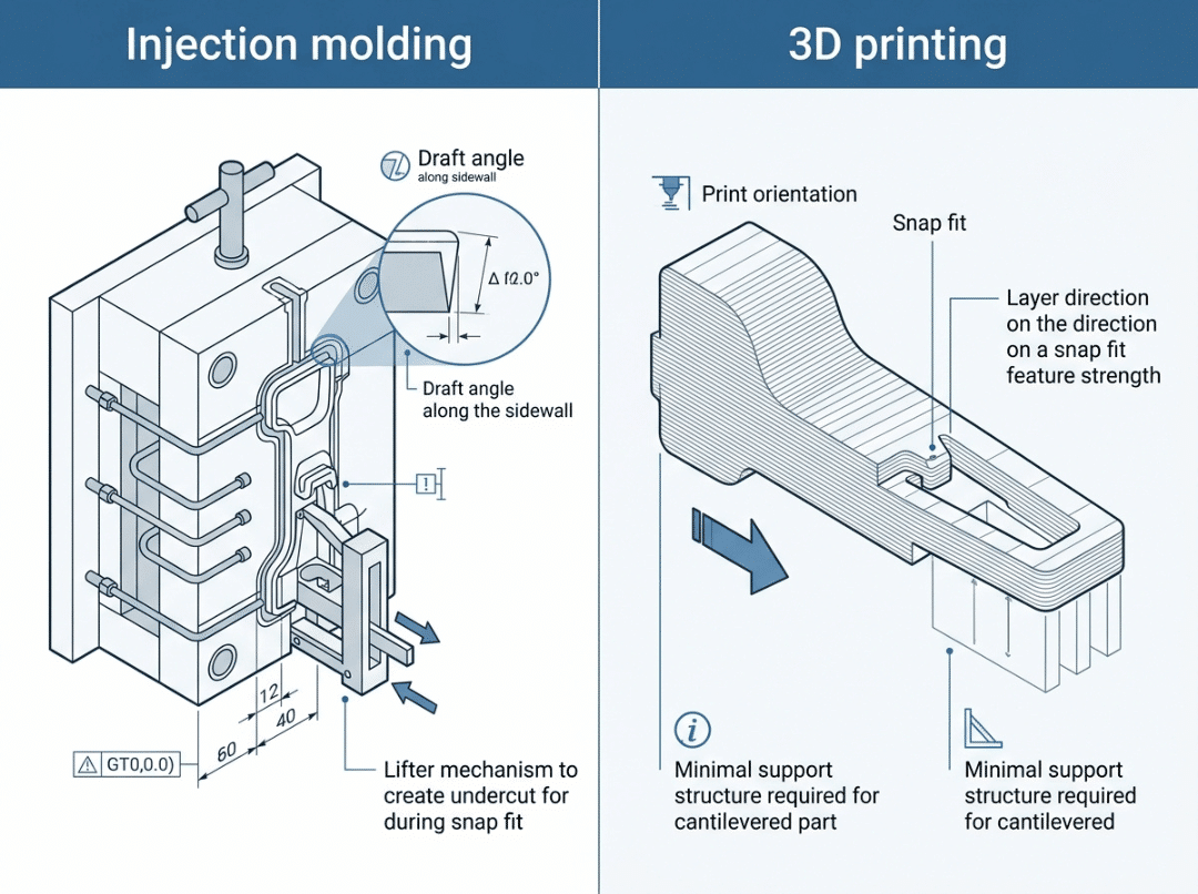
Injection molding
Undercut and ejection strategy: a snap hook is an undercut by definition. Small undercuts on flexible materials can strip off the core during ejection. Larger ones require side actions or lifters, which add tooling cost and lead time. Decide the ejection approach during design — not after the mold is already cut.
Consistent wall thickness: thick sections cool more slowly and sink. Keep arm thickness consistent with the surrounding wall to avoid sink marks and warp near the root.
Shrinkage: the mating gap in the drawing is not the gap in the molded part. Account for material-specific shrink so the assembled fit lands where the design intends. This is especially important for tight-clearance snap features.
3D printing
Anisotropy: FDM parts are significantly weaker between layers than within them. A snap arm bending across the layer lines may split along a bond plane under a load it should easily handle. This is not a material weakness — it is a process behavior that orientation can prevent.
Print orientation: rotate the arm so bending stress runs along the layers. This single decision frequently determines whether a printed snap survives the first assembly.
Strength prediction: FDM prototypes typically underperform equivalent injection-molded parts in fatigue and impact resistance. A printed snap that cracks may still represent a geometry that is perfectly sound in the production material. A printed snap that passes may hide a geometry problem that only shows up in the higher-cycle, higher-load production environment.
Iteration value: printing lets you test multiple arm lengths, fillet sizes, and hook angles in a day before committing to tooling. Use that advantage deliberately.
Moving from prototype to production
When the manufacturing process changes, re-verify the design against the actual production material, account for real shrinkage in the mating gap, and test fresh production samples before signing off. A prototype builds confidence. It does not replace production validation.
Snap Fit DFM Checklist
Work through this before releasing any snap fit design for tooling or production printing.
Geometry
- Root fillet added — radius at least 0.5× the base arm thickness
- Arm tapered toward the tip to distribute strain more evenly along the beam
- Arm length sufficient to keep root strain below the material’s allowable limit
- Lead and return angles set for the required assembly effort and retention behavior
- Undercut depth derived from allowable strain, not chosen by feel or convention
Material and duty cycle
- Material matched to one-time or repeated-use requirement
- Creep resistance evaluated if the joint carries standing load when latched
- Fatigue resistance evaluated for the expected number of open-close cycles
- Working root strain confirmed below the material’s published allowable value
Process
- Draft, ejection method, and undercut strategy confirmed for injection molding
- Print orientation set for layer-aligned bending if 3D printed
- Mating gap designed with shrinkage and tolerance stack accounted for
Validation
- Root strain calculated analytically; FEA completed for critical applications
- Prototype tested for insertion force, retention strength, and surface condition after assembly
- Repeated-cycle test completed if the joint will be opened and closed in service
Snap Fit Design FAQ
What is the allowable strain for a snap fit?
It depends on the material and the duty cycle. For one-time assembly, use the material’s published one-time allowable strain — typically 2% to 8% depending on the resin. For repeated-use joints, design well below that figure to leave fatigue margin. Always confirm with the specific resin’s datasheet rather than relying on generic tables.
How do I reduce insertion force without losing retention?
Reduce the lead angle so the arm enters more gently, and keep the return angle steep to maintain hold. Lengthening or tapering the arm also directly lowers deflection force. These adjustments reduce insertion effort without significantly affecting retention.
Which material works best for a reusable snap fit?
PP is the most common choice for repeated-use snaps due to its flex-fatigue resistance. POM works well where stiffness and a firm latch feel also matter. Both handle repeated cycling reliably. Finalize the choice based on the load environment, chemical exposure, and operating temperature range.
Why is my snap fit loosening over time?
Most likely creep. If the joint carries a sustained load when latched, a creep-prone plastic will slowly relax and retention will fade. The fix is to redesign the joint so it carries little or no standing load once seated — the snap closes, but the surrounding geometry takes the load. Switching to a lower-creep material such as POM or PA is the other option.
How thick should a cantilever snap arm be?
Thin enough that root strain stays within the material’s limit for the chosen arm length, and no thicker. Since strain rises with root thickness, a thinner root is safer on strain but produces a softer hold. Taper the arm toward the tip and always add a root fillet, regardless of thickness.
Can snap fits be made from metal?
Yes. Metal snap fits suit high-load or high-temperature applications where plastic would creep or soften. Metal tolerates much less strain before yielding permanently, so designs run to larger radii and smaller deflections. For most consumer and industrial plastic products, plastic remains the practical default.
What tolerances should a snap fit joint use?
Apply the tightest tolerance to the mating undercut, since that dimension controls both fit and retention. Cosmetic surfaces can run looser. For molded parts, account for material shrinkage. For printed parts, account for dimensional variation inherent to the process. Add locating features so tolerance drift does not accumulate where the snap must seat reliably.
Conclusion
A snap fit’s service life is determined almost entirely by how well the design manages strain. Keep root strain inside the material’s allowable limit, fillet the corner properly, and match the material to how the joint will actually be used — those three decisions resolve the majority of snap fit failures before the design leaves CAD.
To carry forward:
- Snap fit design is a strain problem first. Every geometry choice either helps or hurts that constraint.
- For cantilevers: a longer arm, a tapered cross-section, and a generous root fillet prevent most failures. These are not refinements — they are the baseline.
- Material selection should weight creep and fatigue resistance ahead of stiffness for any joint that carries standing load or opens repeatedly.
- A geometry that works in one manufacturing process may behave quite differently in another. Design for the process you will actually ship.
- Validate analytically, then with a physical prototype. The formula confirms the design is plausible; the prototype confirms it holds up under real conditions.
Before committing to tooling or a production run, a DFM review covering arm geometry, root fillet, undercut sizing, strain, and material choice will surface the issues that are straightforward to correct now and expensive to correct after parts are made.