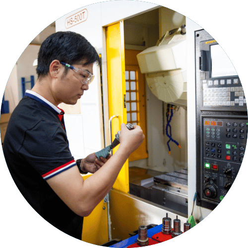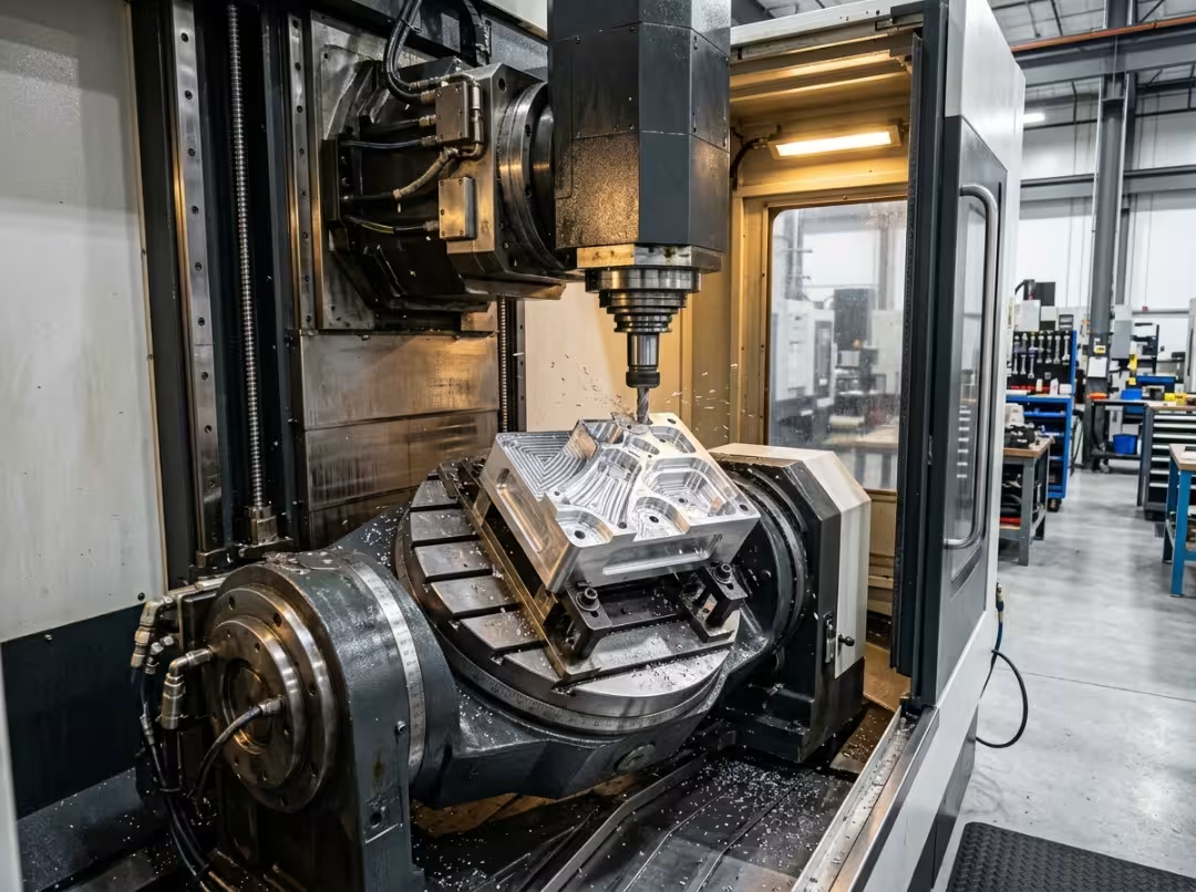
Most shops running a 5-axis machine are actually running two different processes—sometimes without realizing it. The hardware is identical: the same trunnion, the same spindle, the same rotary axes. What changes is the strategy, and that changes everything. Cycle time, tool life, surface finish, programming risk, cost per part—all of it shifts depending on whether you run simultaneous 5-axis or 3+2. Pick wrong, and the margin disappears in ways that never show up on the job traveler.
This article covers where the two strategies genuinely diverge, what that means for how you quote and set up work, and how to pick the right one for the part in front of you.
The Two Strategies, Fast
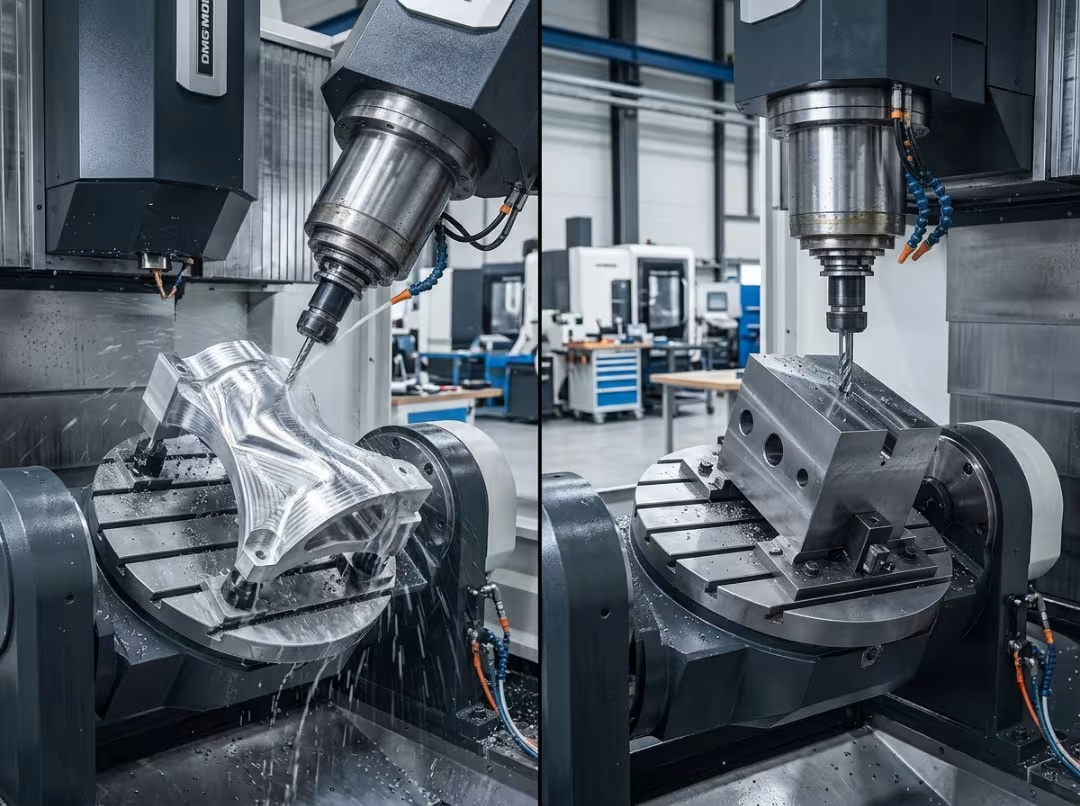
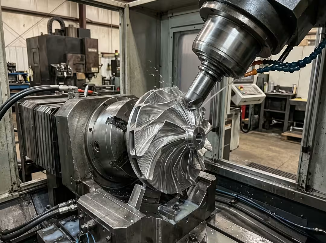
Simultaneous 5-axis keeps all five axes moving while the tool cuts. X, Y, Z, and both rotary axes work in continuous coordination, reorienting the tool throughout the cut to stay aligned with the surface. This is what most people mean by “full 5-axis.” It’s the strategy for impellers, blisks, turbine blades, and sculpted medical implants—geometry that curves in several directions at once and can’t be followed with a fixed approach angle.
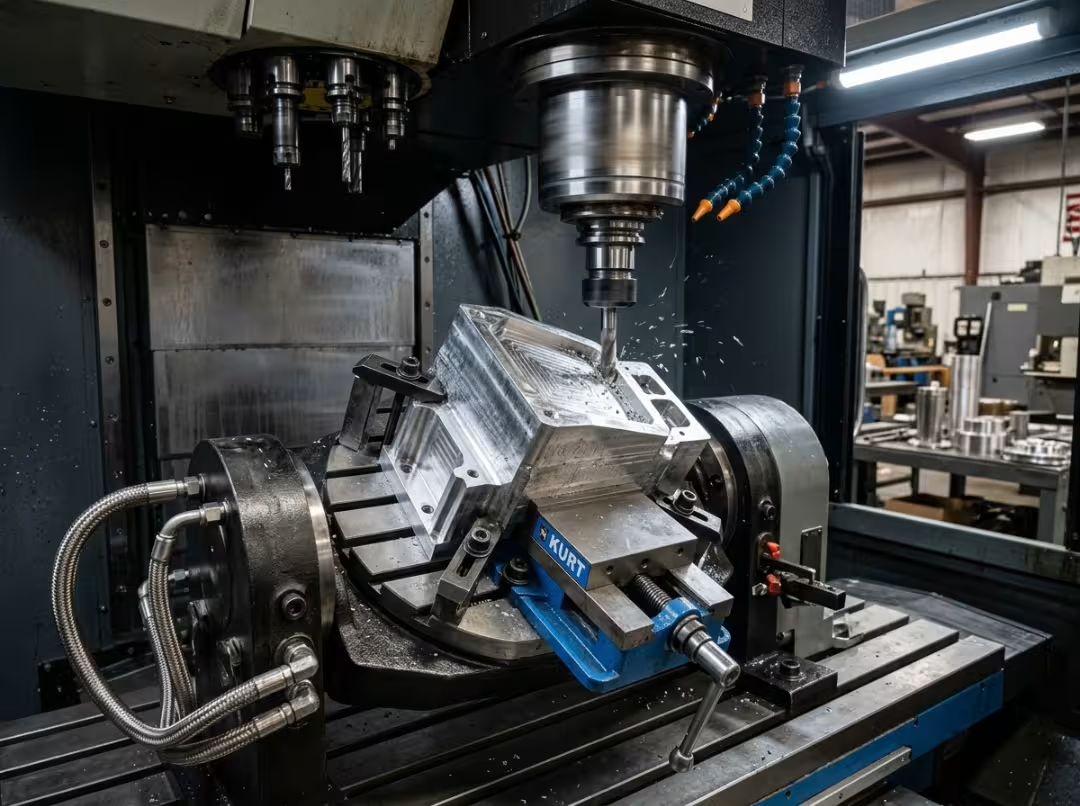
3+2 machining—also called positional, indexed, or 5-sided—works differently. The two rotary axes tilt the part to a fixed angle and lock. The cut then runs as a standard 3-axis move; only X, Y, and Z are in motion. The rotary axes reposition between faces but hold still during each cut. This is the strategy for prismatic housings, valve bodies, brackets, mold cores, and anything with flat faces or angled holes across multiple planes.
One fact drives everything that follows: in simultaneous, the tool vector is always changing; in 3+2, it’s locked before the cut starts. Every meaningful difference—tool wear, surface quality, cycle time, programming complexity—traces back to that.
Where the Two Strategies Actually Diverge
The real cost of getting this wrong shows up in the scrap bin, on the surface grinder, and in the hours your programmer spends fighting a strategy that was never suited to the part.
Access and Tool Orientation
Both strategies reach geometry a 3-axis machine can’t touch, but through different mechanisms. In 3+2, you tilt the part until the feature faces the spindle. Undercuts, angled bosses, side-face features—all become accessible. But once tilted, the machine runs a flat 3-axis job at that angle: one fixed approach vector, straight-line passes.
Simultaneous does something 3+2 fundamentally cannot. A continuously changing tool vector can follow curvature that bends in multiple directions at once—the swept surface of an impeller vane, the leading edge of a turbine blade. No series of fixed tilts approximates that cleanly. You get facets, and you pay for them in bench time.
This is the root of every trade-off below. Tool life, finish, and cycle time all follow from one question: does the vector need to move during the cut, or can it hold still?
Tool Life and Rigidity
Constant engagement angle means predictable wear. In 3+2, the cutter loads evenly through each pass—wear is steady and plannable. In simultaneous, the engagement angle shifts continuously, loading the cutter unevenly. Tool life becomes harder to predict and often shorter.
The more practical 3+2 advantage is rigidity. Instead of reaching around a feature with a long tool, you tilt the part so the feature faces the spindle, then cut it with a short, stiff tool. A deep pocket on an angled face that would need an extended end mill in 3-axis becomes a stubby-tool job in 3+2—less deflection, less chatter, tighter tolerances, and a cutter that lasts.
Simultaneous rarely allows that trade. Complex surfaces force longer reaches, ball-nose cutters, tapered geometries—tools that cost more and wear faster. On genuinely freeform work, that’s unavoidable. But if a feature could be brought within reach of a short, tiltable tool, running simultaneously there adds tooling cost for no reason.
Surface Finish and Accuracy
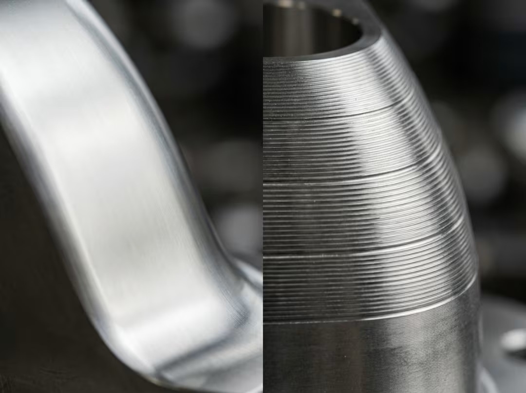
On prismatic features, 3+2 wins on both finish and accuracy. Constant engagement angle produces consistent surfaces, and a locked part means the machine isn’t fighting rotary-axis compliance while trying to hold a positional tolerance on a drilled port or tapped hole. For a valve body with faces that need to be square within a few microns, the locked vector is what makes that reliable.
On freeform geometry, simultaneous wins—with conditions. A well-tuned toolpath produces smooth, continuous finish across sculpted surfaces and can eliminate most hand-finishing. A poorly tuned one, or a machine with worn rotary dynamics, leaves visible facet lines that can be worse than a clean 3+2 pass. The strategy delivers when the CAM work and machine condition are both up to the task.
The honest summary: 3+2 is more forgiving on dimensional accuracy. Simultaneous is the right tool for complex surface geometry, but only when execution is solid. Run simultaneous across a flat face, and you introduce unnecessary surface variation. Run 3+2 across a compound curve, and you get stepped facets that can’t be programmed away. The choice of strategy is also a factor that determines which CNC machining surface-finish outcomes are realistically achievable for a given part.
Cycle Time
Simultaneous runs without stopping. No indexing pauses, no repositioning between faces—the machine stays in cut. On a complex sculpted part, that continuity reduces the total runtime.
3+2 breaks the job into faces. Every transition requires the rotary axes to index, and that dead time accumulates on a part with many faces. Each individual cut, though, runs at full 3-axis speed—higher feeds, more aggressive depths, none of the overhead that continuous vector management imposes.
The practical rule: complex curved parts finish faster with simultaneous because the geometry rewards continuous motion. Multi-face prismatic parts finish faster with 3+2 because aggressive straight cutting outweighs the indexing penalty. Fight the geometry in either direction, and you pay for it.
Programming Reality: What Changes at the CAM Seat
The strategy decision shows up in three ways at the CAM seat: programming time, crash risk, and the skill level the work actually requires.
3+2 is accessible. You apply standard 3-axis toolpaths to a tilted work plane—most packages handle that with a simple transformation. A solid 3-axis programmer can get productive in 3+2 quickly because the motion logic hasn’t changed, only the plane it runs on.
Simultaneous is a different discipline. Full 5-axis strategies—swarf milling, surface flow, multi-surface machining—require a programmer who thinks in terms of tool vectors, anticipates collisions that the software won’t catch, and understands how rotary dynamics affect finish. That’s harder to hire for and longer to develop in-house, and it affects how long it takes to diagnose a bad result.
The post-processor is where risk turns expensive. Both methods need rotary output, but simultaneous demands a genuine 5-axis post that handles continuous rotary motion and vector changes correctly. A mismatched post is one of the most reliable ways to crash a machine and scrap a blank—rotary axes lag linear motion, the tool gouges on the first curved pass, and you lose a day of setup and a workpiece in seconds. Validate the post with a test cut in scrap before it touches anything that matters.
Machine simulation is mandatory for simultaneous. Five axes moving together create collision scenarios that don’t appear on screen without it. For 3+2, the risk is lower, but a simulation check on fixture clearance and rotary positioning is still cheaper than a single crash.
What It Actually Costs Per Part
Shops often ask which strategy needs a more expensive machine. Neither does—it’s the same machine. The real cost gap lives in programming hours, tooling consumption, scrap rate, and cycle time, and those compound differently depending on geometry and volume.
For short runs and complex one-offs, simultaneous often wins on total cost despite the programming overhead. It eliminates setups, removes fixturing complexity, and finishes geometry that would otherwise take hours at the bench. On a single impeller, the programming time is a small fraction of the job value, and the setup savings are large.
For medium-to-high volume prismatic work, 3+2 wins. Shorter tooling costs less and lasts longer. Higher feeds cut cycle time. Simpler programs mean fewer hours amortized across the run. In a batch of several hundred housings, each of those advantages compounds.
The break-even is the point where simultaneous’s setup savings and hand-finishing avoidance pay back its programming overhead. Below that threshold—simpler geometry, higher volume—3+2 is hard to beat on economics. Above it—complex surfaces, low volume—simultaneous earns its keep. Don’t assume; run the numbers for the actual part. If you’re sourcing 5-axis work rather than running it in-house, Essengold’s CNC milling service covers both strategies across a broad range of materials and part types.
How to Choose: A Decision Framework
Three filters, in order. Most decisions settle before the third.
Geometry first. It’s the strongest signal. Freeform surfaces with curvature running in multiple directions point to simultaneous—a locked vector can’t follow them cleanly. Flat faces, angled holes, and features on defined planes point to 3+2. Reference cases: an impeller needs simultaneous because the vane surfaces twist in ways no fixed angle can trace. A valve body wants 3+2 because its features sit on distinct flat faces where a locked vector gives better accuracy and speed.
Then volume and mix. Low-volume, high-mix shops lean toward 3+2—programs write fast, setups stay simple, and you’re not amortizing heavy programming time across a handful of parts. High-volume runs of genuinely complex geometry justify the simultaneous investment.
Then fixturing. 3+2 typically needs simpler fixturing because the machine handles orientation—the part just needs to be held rigidly. Simultaneous can require custom fixturing to keep the part clear of the spindle across the full range of rotary travel.
Applied to real parts: a valve body is prismatic—flat faces, threaded ports, cross-drilled holes. Volume is a steady production batch. Fixturing is a vise. All three filters point to 3+2. An impeller is pure freeform curvature. Volume is low and specialized. Continuous rotary travel needs clearance fixturing. All three filters point to simultaneous. When the filters conflict—complex geometry at high volume—geometry usually wins. You can’t substitute fixturing creativity for access a strategy physically can’t provide.
Quick industry reference:
- Aerospace: structural brackets and housings in 3+2; blisks, vanes, and flow-path geometry in simultaneous.
- Medical: organic implants in simultaneous; instruments, guides, and fixation hardware in 3+2.
- Mold and die: sculpted cavity finishing in simultaneous; core roughing and pocket work in 3+2.
- Automotive: engine housings and prismatic components in 3+2; complex prototypes and near-net cast shapes in simultaneous.
Force the wrong process and the penalty is concrete: long cycles, poor surface quality, or programming hours spent working around geometry the strategy was never designed to handle.
Why Most Shops Run Both
The practical answer is rarely a clean either/or. Most shops use both strategies—often in the same program—because the real question isn’t which process to use for a job. It’s which process to use for each feature.
The standard workflow: rough the part and machine its prismatic features in 3+2, with rigidity and straight-line cutting speed as priorities. Switch to simultaneous only for the surfaces that genuinely need a changing tool vector. You pay the simultaneous overhead—longer programming, slower toolpaths, faster tool wear—only where no cheaper option exists.
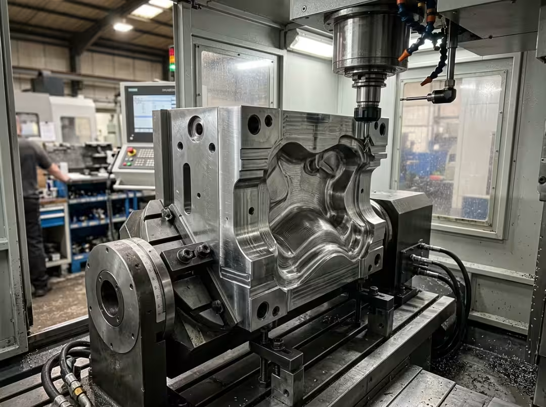
A mold tool is the clearest example. You rough the block in 3+2: fast material removal, short rigid tooling, predictable wear. The flat parting lines, locating features, and bolt holes go in 3+2 as well—locked part, tight positional tolerances. Then the sculpted cavity surface gets finished simultaneously, because that’s the only way to produce the blend quality the mold requires without a polishing shift. One setup, both strategies, each applied where it earns its keep.
That’s what the decision framework points to in practice. You’re rarely choosing a single process for an entire part—you’re choosing the right process for each feature, and holding that line is what keeps the quote competitive.
Frequently Asked Questions
Is 3+2 machining cheaper than simultaneous 5-axis?
For most prismatic and higher-volume work, yes. Cheaper tooling, faster programming, and higher feed rates lower cost per part. For complex low-volume geometry, the math can flip: simultaneous eliminates setups and bench time that would cost more than the extra programming.
What types of parts actually require simultaneous 5-axis?
Parts with continuous curvature in multiple directions—impellers, blisks, turbine blades, organic medical implants. If the surface bends in ways no fixed tool angle can follow without visible faceting, simultaneous is the only option. Prismatic parts rarely, if ever, require it.
Do I need different CAM software or a separate post-processor for each?
Most packages handle 3+2 through a standard work-plane transformation. Simultaneous needs full 5-axis toolpath modules, often a separate license. The post matters more: simultaneous requires a genuine 5-axis post managing continuous rotary motion. Running a simultaneous program through the wrong post is a primary cause of crashes. Validate with a test cut before production.
Which process gives a better surface finish?
It depends on the surface. 3+2 produces a better finish and tighter positional accuracy on flat and prismatic features. Simultaneous produces better finish on freeform blended geometry. Applied to the wrong surface type, each strategy becomes a liability.
Can the same machine do both?
Yes—that’s the point. Both strategies run on the same 5-axis machine, and most shops use both within a single program, switching as the part geometry demands.
Conclusion
The distinction reduces to one fact: simultaneous keeps the tool vector moving throughout the cut; 3+2 locks it before the cut starts. Tool life, surface finish, cycle time, programming complexity, cost per part—all of it follows from that. Once you see the two strategies that way, the comparison stops being a feature list and becomes a routing decision.
The machine is the same either way. What changes is how you use it—driven by geometry first, volume second, programming skill third. When a job sits on the fence, don’t default to the more complex strategy. Run the part both ways, compare cycle time, finish, and per-part cost, and let the numbers decide. For shops looking to put either strategy to work on real production parts, Essengold’s CNC machining service handles both—across metals, plastics, and complex geometries.