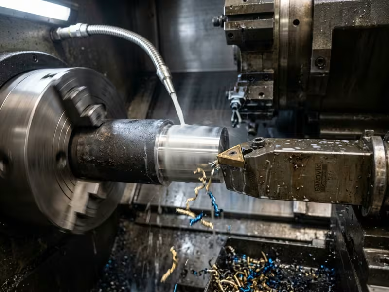
I watched an operator set a 0.003″ finishing pass on a stainless steel bore. The insert rubbed instead of cutting. The bore came out glazed and undersize.
He raised the depth to 0.010″. The next part hit size with a clean finish.
Depth of cut is the thickness of material the tool removes in one pass.
That one number drives cutting force, surface finish, tool life, and cycle time.
I’ll explain what depth of cut means, how to calculate it, and how to choose the right value for your next job.
What Depth of Cut Really Means
Depth of cut is the thickness of material the tool removes in one pass. You measure it at a right angle to the surface you’re cutting.
Where you measure it depends on the machine.
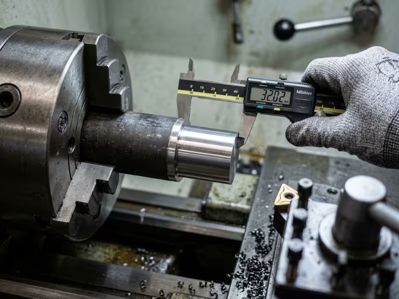
On a lathe, depth of cut runs radially, from the outside diameter toward the center. Take 0.050″ off the radius, and the diameter shrinks by 0.100″. That doubling trips up new operators more than any other point.
On a mill, the main depth runs axially, along the length of the end mill. Step down 5 mm into a block, and 5 mm of the flutes do the work. Mills also have radial engagement, which sets how much of the cutter’s width touches the part. I’ll come back to that when we get to the math.
Shops label it a few ways. ISO cutting data uses ap, and some textbooks write just a. On the shop floor, you’ll hear DOC or AP. Imperial shops measure it in inches. Metric shops use millimeters.
Depth of cut never works alone. Cutting speed and feed rate shape every cut alongside it:
|
Parameter |
Symbol |
Typical unit |
What it controls |
|---|---|---|---|
|
Cutting speed |
Vc |
SFM or m/min |
Edge speed and heat |
|
Feed rate |
f |
in/rev or mm/rev |
Chip thickness and finish |
|
Depth of cut |
ap |
in or mm |
How much edge engages |
Here’s how I explain it to new machinists. Speed sets how fast the edge moves. Feed sets how thick each chip gets. Depth of cut sets how much of the edge goes to work. Change one, and the other two feel it.
Why Depth of Cut Matters on the Machine
Change the depth of cut, and the whole cut changes with it. Force rises first. Heat, deflection, finish, and cycle time all follow. I treat depth as the first link in a chain, because every problem I trace on the shop floor starts there.
Let’s follow that chain from the cutting edge outward.
More Depth Means More Force, More Heat, and Shorter Edge Life
Cutting force grows almost in step with depth of cut. Double the depth at the same feed, and you roughly double the load on the edge. The spindle has to push twice as much material out of the way.
That extra work turns into heat. Most of it leaves with the chip, but the edge still takes its share. In steel, a hotter edge wears faster on the flank and can crater on the top face. In titanium and stainless, heat builds even faster because the material holds it near the cut.
Here’s the part many people miss. Of the three cutting parameters, depth of cut usually hurts tool life the least. Speed hurts it the most. So when I need to remove more metal, I add depth before I add speed. A carbide insert running 0.120″ deep at a sensible speed often outlasts the same insert at 0.060″ with the speed pushed hard.
That force doesn’t stop at the insert, though. It travels into the tool, the holder, and the part.
Heavy Cuts Bend Things, and Bending Shows Up on the Part
Every setup flexes a little under load. A boring bar sticking out 4× its diameter, a thin-walled sleeve, or a long end mill all bend away from a heavy cut. When the tool pushes off, it leaves material behind. The part measures oversize, or the wall comes out tapered.
Push the load far enough, and the flex turns into vibration. That’s chatter: a loud squeal and a wavy, rippled surface. Once chatter starts, it chips edges and ruins the finish.
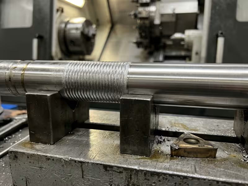
Light cuts keep the force low, so the tool cuts where you told it to. That’s why I always leave a finishing pass. On a typical turned steel part, I rough to within about 0.010–0.020″ per side, then take one light pass to hit size and finish.
Too light causes trouble too. If the depth drops well below the insert’s nose radius, the edge rubs instead of cutting. You get glazing, work hardening, and poor size control.
Finish and accuracy pull you toward lighter cuts. Productivity pulls the other way.
Deeper Cuts Remove Metal Faster, Until the Setup Says No
Material removal rate (MRR) shows how much metal you clear per minute. In turning, it equals cutting speed × depth of cut × feed. Take steel at 200 m/min with a 0.25 mm/rev feed:
- At 2 mm depth, you remove about 100 cm³ per minute.
- At 4 mm depth, you remove about 200 cm³ per minute.
Double the depth, and you double the output. Fewer passes also mean fewer tool moves and less air cutting, so cycle time drops even more.
That gain holds only while the setup can take it. Past a certain point, extra depth brings chatter, broken inserts, or a stalled spindle. A ruined part or a crashed tool wipes out every second you saved. The best depth of cut removes metal as fast as your machine, tool, and part can handle without losing size or finish.
How to Calculate Depth of Cut
The math behind depth of cut is simple. Most mistakes come from measuring the wrong thing, not from bad arithmetic. Each machine measures depth a little differently, so I’ll walk through them one at a time.
Start with the lathe, where the confusion shows up most often.
Turning: Find the Radial Depth From Your Diameters
Whether you run a manual lathe or a CNC turning center, use this formula:
DOC = (initial diameter − final diameter) ÷ 2
Say you turn 50 mm bar stock down to 46 mm. The diameter shrinks by 4 mm, but the tool only cuts into one side of the radius. So your depth of cut equals 4 ÷ 2 = 2 mm.
That divide-by-two step causes more scrapped parts than any other lathe math. Most CNC lathes program the X-axis in diameter. If you move X by 4 mm, the tool travels just 2 mm radially. Now picture an operator who wants a 4 mm roughing pass and moves X by 4 mm. He gets half the cut he planned.
The reverse mistake hurts more. On a control that programs X in radius, an operator who enters an 8 mm move to get “4 mm per side” sends the insert 8 mm deep. That’s twice the depth he planned, and often more than the insert can handle.
I tell new operators to say both numbers out loud: “4 mm off the diameter, 2 mm per side.” It sounds basic, but it saves inserts.
Milling adds a second dimension to the calculation.
Milling: Axial Depth and Radial Engagement
In CNC milling, the cutter works with two depths at once:
- Axial depth (ap) shows how far the end mill reaches down along its axis.
- Radial engagement (ae) shows how much of the cutter’s width touches the material.
Both decide the load on the tool. Here’s how one 12 mm carbide end mill behaves in two common cuts:
|
Cut type |
Axial depth (ap) |
Radial engagement (ae) |
Cutter engagement |
|---|---|---|---|
|
Slotting |
6 mm (0.5× D) |
12 mm (100%) |
Half the cutter circumference |
|
Side milling |
24 mm (2× D) |
1.2 mm (10%) |
About one-tenth |
In a full slot, half the cutter circumference stays buried in metal. Chips have nowhere to go, and heat builds fast. So I keep the axial depth shallow.
In side milling, the tool sees light radial contact. I can run four times the axial depth and spread wear along more of the flute. At 10% engagement, chips also come out thinner, about 60% of the programmed feed per tooth. That lets me raise the feed rate without overloading the edge.
Always check both numbers together. A “safe” 6 mm axial depth can still overload the tool in a full slot.
Drilling, Boring, and Grinding in Brief
In drilling, depth of cut equals half the drill diameter, so a 10 mm drill cuts at 5 mm. Boring uses the turning formula in reverse: subtract the starting bore from the finished bore and divide by two. Grinding works at a much smaller scale. Most passes stay between about 0.005 and 0.05 mm, because the wheel removes metal in thin layers to hold tight size and finish.
What Limits Depth of Cut
A catalog might say an insert can take 6 mm. Your calculator might say you can clear the stock in two passes. Neither one has seen your machine, your fixture, or your part. Before I commit to a roughing depth, I check six real-world limits. The weakest one sets the number.
Spindle power and torque come first. Every cubic centimeter of metal costs power. In steel, a 4 mm turning pass at 200 m/min and 0.25 mm/rev needs about 7–8 kW at the spindle. Run that on a 7.5 kW lathe, and the spindle bogs down or throws an alarm. Torque matters just as much on large diameters. At low RPM, many spindles deliver only a fraction of their rated power, so a heavy cut on a 300 mm part can stall a machine that handles 50 mm bar with ease.
Machine rigidity decides how much force the setup can absorb. A heavy box-way mill shrugs off loads that make a light linear-guide machine ring. Worn gibs, loose ways, and spindle bearing play all cut into your usable depth. If a machine chatters on a cut that runs smoothly on another, the machine is telling you something.
Workholding and part geometry often set the real ceiling. A part sticking out of the chuck more than about three times its diameter needs tailstock support. Thin walls bend away from the tool. Long, slender end mills and boring bars flex too. A steel boring bar works well up to about 4× its diameter in overhang. Past that, I switch to carbide or cut the depth.
Those limits come from the setup. The next two come from the cutting edge and the metal.
Tool geometry caps the depth from both ends. As a rule of thumb, keep depth under about two-thirds of the insert’s cutting edge length. Go deeper, and you load the weak back end of the edge. Go too shallow, below roughly the nose radius, and the insert rubs instead of cutting. Always check the insert box. The toolmaker prints the safe range for a reason.
Material hardness and heat resistance shrink every number. A depth that runs fine in 1018 steel can snap an edge in hardened 4140 at 45 HRC. Titanium and Inconel hold heat at the cut and wear inserts fast. In those alloys, I also vary the depth slightly between passes. That spreads notch wear along the edge instead of grinding one groove at the depth-of-cut line.
Chip evacuation limits deep cuts in tight spaces. In full slots and deep pockets, chips pile up and get recut. Recut chips damage the edge and spike the heat. Through-spindle coolant, air blast, or a shallower step-down keeps the flutes clear.
The usable depth of cut is the smallest number on this list, not the biggest one in the catalog.
How to Choose the Right Depth of Cut
When I set up a new job, I pick the depth of cut in a fixed order. I don’t start with the biggest number the catalog allows, and I don’t guess. I start with the cutting data, shape it to the operation, check it against the setup, and then let a test cut confirm it.
Here’s how that process works on the shop floor.
Step 1: Start With the Toolmaker’s Cutting Data
Every insert box and end mill catalog lists a working range. A general-purpose CNMG roughing insert in steel might show a depth of 1.0–4.0 mm and a feed of 0.15–0.35 mm/rev. The toolmaker designed the chipbreaker to work inside that window.
I start near the middle of the range, not at the top. On an older machine or with a long overhang, I start at about 60–70% of the recommended maximum.
Stay inside the window at the bottom end too. Run below the chipbreaker’s minimum depth, and chips come off long and stringy. They wrap around the part and scratch the finish.
The catalog gives you a baseline. The operation tells you where to land inside it.
Step 2: Rough Heavy, Finish Light
Roughing and finishing have different jobs, so they need different depths.
Roughing should take the largest depth your setup can hold without chatter or overload. Fewer passes mean less cycle time and fewer tool moves. I also split the stock evenly. Say you need to remove 9 mm per side with an insert rated for 4 mm. Don’t run 4, 4, and then 1 mm. Run three passes at 3 mm each. The tool sees a steady load, and that last thin pass doesn’t rub.
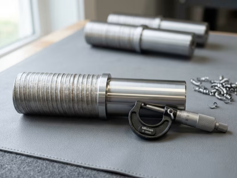
Finishing has one goal: hit size and finish. Keep the depth light enough that the tool barely deflects. On turned steel, I usually leave 0.2–0.5 mm per side, and I keep that depth at or slightly above the insert’s nose radius.
Keep the finishing allowance the same on every part. Then the tool deflects the same amount every time, and the size repeats from part to part. If roughing leaves 0.3 mm on one part and 0.8 mm on the next, your finished size will wander.
Step 3: Check Engagement and Rigidity Before You Commit
On a mill, axial depth tells only half the story. You need to set axial depth and radial engagement together.
My starting rules with a solid carbide end mill look like this:
- Full slotting: keep axial depth at about 0.5–1× the tool diameter.
- Side milling at 10–20% radial engagement: run axial depth up to 1.5–2× the diameter.
- Adaptive or high-efficiency toolpaths: use the full flute length with light radial engagement, often 5–15%.
Then check rigidity. If the tool sticks out more than about 3× its diameter, I cut the axial depth by a third or more. On thin walls, I step down both sides in turns, so the wall always has solid material behind it.
Numbers on paper still need proof at the spindle.
Step 4: Take a Test Cut and Read the Result
I run the first part at about 80% of my planned depth. Then I read four signals:
- Chips. In steel, straw to light blue chips in C or 6-shapes mean a healthy cut. Dark blue or purple chips mean too much heat.
- Sound. A steady hiss is good. A squeal or a low growl means chatter.
- Spindle load. For roughing, I aim to stay under about 80% of the meter.
- Surface. Clean feed marks are fine. Ripples or wavy patterns point to vibration.
If everything looks good, I raise the depth in steps of 10–20% until one signal starts to slip. Then I back off one step.
Too Deep, or the Wrong Feed?
Not every problem calls for a change in depth. Before I touch the depth, I ask which symptom I’m seeing.
|
What you see |
Likely cause |
What to change |
|---|---|---|
|
Spindle load spikes, part pushed oversize |
Depth too deep |
Reduce depth |
|
Chatter that starts as depth rises |
Depth too deep for the setup |
Reduce depth or overhang |
|
Edge chipping at the depth-of-cut line |
Depth too deep or notch wear |
Reduce or vary depth |
|
Long, stringy chips |
Feed too light |
Raise feed |
|
Glazed surface, edge rubbing |
Feed too light |
Raise feed |
|
Deep, regular feed marks |
Feed too heavy |
Lower feed |
Chatter at light radial engagement often clears when I raise the feed slightly. A thicker chip loads the edge and breaks the vibration. If chatter gets worse as depth increases, though, the setup has reached its limit. More feed won’t fix it.
Change one parameter at a time. Then you know exactly which change fixed the cut.
Typical Depth of Cut Ranges by Material and Operation
Machinists often ask me for “the right number.” I give them a starting range instead. The table below shows where I begin with carbide tooling on a rigid, well-maintained machine. Treat every value as a rule of thumb, not a universal spec.
Turning values show radial depth per side. Milling values show axial depth for a 10–12 mm end mill or a face mill at moderate radial engagement.
|
Material |
Operation |
Roughing DOC range |
Finishing DOC range |
Caution note |
|---|---|---|---|---|
|
Mild/alloy steel |
Turning |
2–5 mm |
0.2–0.5 mm |
Watch spindle power on large diameters |
|
Mild/alloy steel |
Milling |
1–4 mm |
0.2–0.5 mm |
Reduce depth for full slots |
|
Aluminum |
Turning |
2–6 mm |
0.2–0.5 mm |
Use sharp, polished inserts to stop built-up edge |
|
Aluminum |
Milling |
3–10 mm |
0.1–0.5 mm |
Clear chips fast, or they weld to flutes |
|
Cast iron |
Turning |
2–5 mm |
0.2–0.5 mm |
Start the first pass below the hard skin |
|
Cast iron |
Milling |
1–5 mm |
0.2–0.5 mm |
Expect abrasive dust, not long chips |
|
Titanium |
Turning |
1–3 mm |
0.2–0.5 mm |
Vary depth between passes to spread notch wear |
|
Titanium |
Milling |
1–3 mm |
0.1–0.3 mm |
Keep radial engagement light and coolant heavy |
Across everyday CNC metal machining, aluminum forgives the most. Titanium forgives the least. Steel and cast iron sit in the middle, but cast iron wears edges through abrasion, not heat.
The toolmaker’s data always wins. If your insert box lists 1.5–3 mm and this table says 2–5 mm, run 1.5–3 mm. The toolmaker tested that chipbreaker and grade together. I don’t.
Then adjust for your setup. I take about 30% off the roughing range for long overhangs, thin walls, light machines, or worn spindles.
For finishing, keep the depth at or slightly above the insert’s nose radius. A 0.4 mm nose radius usually needs at least 0.3–0.4 mm of stock to cut cleanly instead of rubbing.
Use these ranges to start your first test cut. Your chips, spindle load, and surface finish will tell you where to go from there.
Common Depth of Cut Mistakes That Cost You Parts
Most depth-of-cut problems I fix on the shop floor don’t start with a bad tool. They start with a few habits. These five show up most often.
Mixing up diameter and radius on a lathe. An operator wants 3 mm off the diameter but programs a 3 mm radial cut. The insert takes twice the depth he planned, and the part ends up 3 mm undersize. Before you run a pass, confirm whether your control reads X in diameter or radius. Then write both numbers on the setup sheet.
Watching axial depth and ignoring radial engagement. A 6 mm step-down feels safe with a 12 mm end mill. In a full slot, though, that same depth buries half the cutter in metal. Chips pack the flutes, heat spikes, and the tool snaps. Every time you set axial depth, check how much of the cutter’s width touches the part.
Chasing the catalog maximum on a weak setup. A 5 mm roughing pass may suit a heavy box-way lathe. On a light machine with worn gibs or a long overhang, the same pass brings chatter and spindle alarms. Size the cut to your weakest link, not to the insert box.
Skipping the finishing pass to save time. Some programmers rough straight to size. The tool deflects under the heavy load, so the part comes out tapered or oversize with a torn surface. Then the tool takes the blame. Leave 0.2–0.5 mm per side and finish with one light, steady pass. It adds seconds and saves scrapped parts.
Copying another shop’s numbers. A forum post or a colleague’s program shows a depth that “runs great.” But their machine, fixture, and tool stick-out differ from yours. Treat their numbers as a rough guide only. Start at about 80% on your setup, and let the chips, sound, and spindle load confirm the cut.
All five mistakes share one root cause: people trust a number before their own machine proves it.
Depth of Cut FAQ
What is depth of cut in machining?
Depth of cut is the thickness of material the tool removes in one pass. You measure it at a right angle to the surface you’re cutting. On a lathe, it runs radially toward the center. On a mill, the main depth runs along the end mill’s axis.
What is the difference between axial and radial depth of cut?
Axial depth (ap) shows how far the end mill reaches down along its axis. Radial engagement (ae) shows how much of the cutter’s width touches the part.
Both set the load on the tool. In a full slot, the cutter runs at 100% radial engagement, so I keep axial depth near 0.5–1× the tool diameter. At 10% radial engagement, I often run up to 2× the diameter.
How do you calculate depth of cut in turning?
Subtract the final diameter from the starting diameter, then divide by two. Turning 50 mm stock down to 46 mm gives you a 2 mm depth of cut.
Before you run the pass, check whether your control programs X in diameter or radius. That one check prevents most lathe depth errors.
What happens if depth of cut is too large?
Cutting force climbs past what your setup can hold. The tool deflects, and the part measures oversize or tapered. Chatter leaves ripples on the surface.
Push further, and you chip inserts, snap end mills, or trip a spindle overload alarm. When I see these signs, I cut the depth by 20–30% and check tool overhang first.
What is a good depth of cut for aluminum?
With sharp carbide on a rigid machine, I start roughing at 2–6 mm per side in turning and 3–10 mm axial in milling. For finishing, I leave 0.1–0.5 mm.
Aluminum takes heavy cuts well. But you need to clear chips fast, or they weld to the flutes and ruin the finish.
How does depth of cut affect tool life?
Deeper cuts raise force and heat at the edge, so wear speeds up. Still, depth hurts tool life less than cutting speed does. When I need to remove more metal, I add depth before I add speed.
In titanium and Inconel, I vary the depth slightly between passes. That spreads notch wear along the edge instead of grinding one groove into it.
Let Your Machine Confirm the Number
Depth of cut is the thickness of material your tool removes in one pass.
Never judge it on its own. Feed, speed, rigidity, and radial engagement all share the load with it. Change one, and the others shift.
Don’t copy numbers by feel. Pull the toolmaker’s data sheet for your insert or end mill. Start inside that range, run a test cut, and read the chips, sound, and spindle load. Then build your own numbers from there.