


CNC machining tolerances define the allowable variation in a part’s dimensions, ensuring precision and consistency in the manufacturing process. These tolerances play a crucial role in meeting design specifications, ensuring product quality, and ensuring components fit and function as intended. Understanding tolerances is essential for balancing quality, cost, and efficiency, as tighter tolerances often lead to increased production complexity and expenses. By mastering this concept, manufacturers can optimize processes, reduce waste, and deliver reliable, high-performing products.
What Are CNC Machining Tolerances?
Defining CNC Machining Tolerances
CNC machining tolerances refer to the permissible range of variation in a part’s dimensions, as specified by the design or engineering requirements. These tolerances ensure that the final product meets functional and aesthetic standards while maintaining compatibility with other components in an assembly. For example, a tolerance of ±0.01 mm means the actual dimension of the part can deviate by up to 0.01 mm above or below the specified measurement. This small margin of error allows manufacturers to account for minor inconsistencies in the machining process without compromising the part’s performance.
How Tolerances Impact Precision and Manufacturing Outcomes
Tolerances directly influence the precision of CNC-machined parts and the overall success of the manufacturing process. Tight tolerances, which allow for minimal deviation, ensure that parts fit together seamlessly and function as intended in high-performance applications, such as aerospace or medical devices. However, achieving such precision often requires advanced machinery, skilled operators, and additional time, which can increase production costs.
On the other hand, looser tolerances may reduce manufacturing complexity and costs but can compromise the part’s functionality or compatibility in critical applications. For instance, a loose tolerance in a gear assembly might lead to excessive play, noise, or even mechanical failure. Striking the right balance between precision and practicality is essential for optimizing production efficiency, maintaining quality, and controlling costs.
By understanding and specifying appropriate tolerances, manufacturers can ensure that parts meet design requirements while minimizing waste, rework, and delays. This knowledge helps streamline production, improve product reliability, and enhance customer satisfaction.
Types of CNC Machining Tolerances
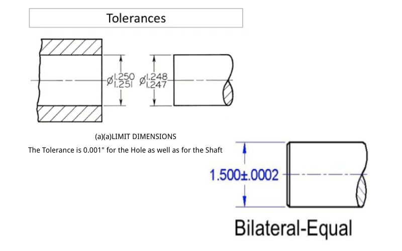
Unilateral, Bilateral, and Limit Tolerances
CNC machining tolerances can be categorized into unilateral, bilateral, and limit tolerances, each serving specific design and manufacturing needs. Unilateral tolerances allow variation in only one direction from the specified dimension. For example, a dimension of 50 mm with a tolerance of +0.02/-0.00 mm means the part can only deviate above the nominal size. This type of tolerance is often used when one side of the dimension is critical for the functionality or assembly of the component.
Bilateral tolerances permit variation in both directions, above and below the nominal size. For instance, a tolerance of ±0.01 mm on a 50 mm dimension means the part can measure between 49.99 mm and 50.01 mm. Bilateral tolerances offer greater flexibility in manufacturing and are commonly employed when the exact center of the tolerance range is not crucial.
Limit tolerances specify the maximum and minimum acceptable dimensions without indicating a nominal size. For example, a part dimension might be defined as 49.98 mm to 50.02 mm. This approach simplifies inspection and ensures that any measurement within the range meets the design requirements. Understanding these tolerance types helps manufacturers choose the most appropriate method for balancing precision and production efficiency.
Profile, Orientation, and Location Tolerances
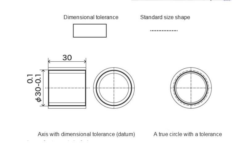
Profile, orientation, and location tolerances focus on the geometric accuracy of a part rather than its linear dimensions. Profile tolerances control the shape of a surface or curve, ensuring that it conforms to the specified design within a defined boundary. For example, a profile tolerance might ensure that a curved surface remains within 0.05 mm of the intended shape, maintaining aerodynamic or aesthetic properties.
Orientation tolerances govern the angular relationship between features, such as parallelism, perpendicularity, or angularity, ensuring accurate alignment. These tolerances ensure that features align correctly, which is crucial for assemblies where precise angles significantly impact functionality. For instance, a perpendicularity tolerance ensures that a hole aligns perfectly with a mating part, preventing misalignment during assembly.
Location tolerances control the position of features, such as holes, slots, or bosses, relative to a reference point or datum. These tolerances ensure that features are placed accurately, maintaining the part’s functionality and compatibility with other components. For example, a location tolerance might specify that a hole’s center must remain within 0.1 mm of its intended position. By managing these geometric tolerances, manufacturers can achieve high levels of precision and ensure that parts meet design and assembly requirements.
Overview of Geometric Dimensioning and Tolerancing (GD&T)
Geometric Dimensioning and Tolerancing (GD&T) provides a standardized framework for defining and communicating tolerances in CNC machining. Unlike traditional tolerancing methods, which focus on linear dimensions, GD&T emphasizes the geometric relationships between features. This approach uses symbols and annotations to specify tolerances for form, orientation, profile, location, and runout, ensuring that parts meet functional and assembly requirements.
GD&T offers several advantages, including improved clarity, reduced ambiguity, and enhanced design flexibility. For example, a GD&T profile tolerance can define the allowable variation of a complex surface, ensuring that it meets aerodynamic or aesthetic criteria without over-constraining the design. Similarly, a position tolerance can control the location of a hole relative to multiple datums, ensuring compatibility with mating parts.
By adopting GD&T, manufacturers can optimize their designs for functionality and manufacturability, reduce inspection time, and improve communication between design and production teams. This system plays a crucial role in modern CNC machining, enabling the production of high-precision parts that meet stringent quality standards.
How to Calculate and Express Tolerances
Key Terms: Basic Size, Actual Size, Limits, and Deviations
Understanding key terms is essential for calculating and expressing tolerances accurately. The basic size refers to the nominal dimension specified in the design, serving as the starting point for tolerance calculations. The actual size represents the measured dimension of the manufactured part, which must fall within the specified tolerance range to meet quality standards.
Limits define the maximum and minimum allowable dimensions for a part. For example, if a part has a basic size of 50 mm with a tolerance of ±0.02 mm, the upper limit is 50.02 mm, and the lower limit is 49.98 mm. Deviations indicate the difference between the basic size and the actual size. The upper deviation represents the difference between the basic size and the maximum limit, while the lower deviation shows the difference between the basic size and the minimum limit. These terms provide a clear framework for defining and evaluating tolerances in CNC machining.
Step-by-Step Guide to Calculating Tolerances with Examples
Calculating tolerances involves determining the permissible range of variation for a part’s dimensions. Follow these steps to calculate and express tolerances effectively:
- Identify the Basic Size
Start with the nominal dimension specified in the design. For example, if the design calls for a shaft with a diameter of 20 mm, this becomes the basic size. - Determine the Tolerance Range
Define the allowable variation based on the design requirements or industry standards. For instance, if the tolerance is ±0.01 mm, the part can deviate by 0.01 mm above or below the basic size. - Calculate the Limits
Add and subtract the tolerance value from the basic size to determine the upper and lower limits. Using the previous example, the upper limit is 20.01 mm (20 mm + 0.01 mm), and the lower limit is 19.99 mm (20 mm – 0.01 mm). - Express the Tolerance
Represent the tolerance in a clear and standardized format. For bilateral tolerances, use the ± symbol (e.g., 20 mm ±0.01 mm). For unilateral tolerances, specify the direction of variation (e.g., 20 mm +0.01/-0.00 mm). For limit tolerances, list the maximum and minimum dimensions (e.g., 19.99 mm to 20.01 mm).
Example Calculation
Suppose a design specifies a hole with a basic size of 10 mm and a tolerance of +0.02/-0.01 mm. To calculate the limits:
- Upper Limit: 10 mm + 0.02 mm = 10.02 mm
- Lower Limit: 10 mm – 0.01 mm = 9.99 mm
Express the tolerance as: 10 mm +0.02/-0.01 mm or 9.99 mm to 10.02 mm.
By following these steps, manufacturers can ensure that tolerances are calculated and expressed clearly, reducing ambiguity and improving communication between design and production teams. This process helps maintain precision, optimize quality, and streamline manufacturing operations.
Common CNC Machining Tolerances by Process
Standard Tolerances for Milling, Turning, and Engraving
Each CNC machining process comes with its own standard tolerances, which depend on the machine’s capabilities, the tools used, and the complexity of the design. Milling, a versatile process for creating flat surfaces, slots, and intricate geometries, typically achieves tolerances of ±0.1 mm for general applications. High-precision milling can tighten tolerances to ±0.01 mm, especially when using advanced machines and optimized cutting parameters. Factors like tool wear, spindle speed, and material hardness influence the achievable precision.
Turning, which involves rotating the workpiece while a cutting tool removes material, often delivers tighter tolerances compared to milling. Standard turning tolerances range from ±0.05 mm to ±0.01 mm, depending on the part’s size and complexity. Turning excels in producing cylindrical parts, such as shafts and bushings, where concentricity and surface finish are critical. Proper tool selection and consistent cutting speeds ensure precise results.
Engraving, used for marking or adding fine details to parts, generally operates with tolerances of ±0.1 mm. While engraving prioritizes aesthetics and readability over dimensional accuracy, advanced machines can achieve tighter tolerances for intricate designs. The depth and clarity of engraved features depend on factors like tool sharpness, feed rate, and material properties. By understanding the standard tolerances for each process, manufacturers can select the most suitable method for their specific requirements.
| Table 1: Standard Machining Tolerances for Different Manufacturing Processes | |
| Processes | Standard Tolerance |
| CNC lathe cutting | ±0.005″ |
| 3-Axis CNC milling | ±0.005″ |
| 5-Axis CNC milling | ±0.005″ |
| CNC routing | ±0.005″ |
| 3D printing | ±0.004″ |
| Engraving | ±0.005″ |
| Gasket cutting | ±0.030″ |
Comparing Tolerances for Different Materials
The material being machined significantly affects the achievable tolerances, as different materials respond differently to cutting forces, heat, and tool interaction. Metals, such as aluminum, steel, and titanium, generally allow for tighter tolerances due to their rigidity and predictable machining behavior. For example, aluminum parts can achieve tolerances as tight as ±0.01 mm in milling or turning, thanks to its machinability and thermal stability. Steel, while more rigid and more durable, may require slower cutting speeds and specialized tools to maintain similar precision.
Plastics, on the other hand, present unique challenges that often result in looser tolerances. Materials like ABS, nylon, and polycarbonate tend to deform under cutting forces or heat, making it harder to achieve tight tolerances. Standard tolerances for plastic parts typically range from ±0.1 mm to ±0.2 mm, depending on the material’s properties and the machining process. For instance, softer plastics may require lower feed rates and sharper tools to minimize deformation and ensure consistent results.
When comparing metals and plastics, manufacturers must consider factors such as thermal expansion, material hardness, and surface finish requirements. Metals generally offer better dimensional stability, making them ideal for high-precision applications. Plastics, although less precise, offer advantages such as lightweight construction and corrosion resistance, making them suitable for specific industries. By tailoring machining processes and tolerances to the material, manufacturers can optimize quality and efficiency while meeting design specifications.
Factors Influencing Tolerances
Material Properties and Machinability
The properties of the material being machined play a significant role in determining achievable tolerances. Harder materials, such as stainless steel or titanium, resist cutting forces but may cause faster tool wear, making it challenging to maintain tight tolerances over extended production runs. Softer materials, such as aluminum, offer excellent machinability and allow for tighter tolerances; however, they can deform under high cutting forces if not handled carefully. Plastics, on the other hand, often expand or contract due to heat generated during machining, which can lead to dimensional inaccuracies. For example, polycarbonate may warp or shrink, requiring slower feed rates and precise cooling to maintain tolerances. Understanding the material’s hardness, thermal conductivity, and elasticity enables manufacturers to adjust machining parameters and achieve the desired precision.

Machine Capabilities and Tooling
The capabilities of the CNC machine and the tools used directly impact the tolerances that can be achieved. High-precision CNC machines equipped with advanced control systems and rigid structures can consistently deliver tighter tolerances, often within ±0.01 mm. Older or less sophisticated machines may struggle to maintain such precision, especially during complex operations. Tooling also plays a critical role; sharp, high-quality cutting tools reduce vibration and ensure clean cuts, which are essential for maintaining tight tolerances. Tool wear, however, can compromise accuracy over time, making regular tool inspection and replacement necessary. Additionally, the choice of tool material, such as carbide or diamond-coated tools, affects performance, especially when machining hard or abrasive materials. By matching machine capabilities and tooling to the specific requirements of the job, manufacturers can optimize precision and efficiency.
Environmental Factors Like Temperature and Humidity
Environmental conditions, such as temperature and humidity, can significantly influence machining tolerances, particularly in high-precision applications. Temperature fluctuations cause materials to expand or contract, leading to dimensional changes that affect the final part. For instance, a steel workpiece may expand slightly in a warm environment, resulting in measurements that deviate from the intended tolerances. Similarly, high humidity levels can lead to condensation on the machine or workpiece, potentially causing rust or affecting the cutting process. To mitigate these effects, manufacturers often control the machining environment by maintaining stable temperatures and humidity levels. Using climate-controlled facilities and monitoring environmental conditions ensures consistent results, especially for materials sensitive to thermal expansion or moisture. By addressing these factors, manufacturers can maintain tighter tolerances and improve overall part quality.
When to Use Tight Tolerances
Scenarios Requiring Tight Tolerances
Certain industries and applications demand tight tolerances to ensure functionality, safety, and reliability. In the aerospace sector, components like turbine blades, engine parts, and structural elements must meet extremely precise specifications. Even minor deviations can compromise performance, lead to mechanical failure, or jeopardize safety. For example, a turbine blade with a tolerance of ±0.01 mm ensures optimal airflow and efficiency, while tighter tolerances in fasteners prevent vibration and maintain structural integrity during flight.
Medical devices also rely heavily on tight tolerances to ensure accuracy and compatibility. Surgical instruments, implants, and diagnostic equipment require precision to function correctly and meet stringent regulatory standards. For instance, a prosthetic joint must fit perfectly to avoid discomfort or failure, while diagnostic tools like CT scanners depend on precisely machined components to deliver accurate results. In these scenarios, tight tolerances not only enhance performance but also ensure compliance with industry regulations and patient safety.
Other industries, such as automotive manufacturing, semiconductor production, and precision engineering, also benefit from tight tolerances. High-performance engines, microchips, and optical components require exact dimensions to achieve their intended functionality. By maintaining tight tolerances, manufacturers can meet the demands of these critical applications and deliver products that perform reliably under challenging conditions.
Balancing Precision with Cost and Production Time
While tight tolerances improve precision and functionality, they also increase production complexity, cost, and time. Achieving tighter tolerances often requires advanced machinery, specialized tooling, and slower machining speeds, all of which add to manufacturing expenses. For example, producing a part with a tolerance of ±0.01 mm may involve multiple quality checks, tool replacements, and adjustments to ensure consistency, driving up costs and extending lead times.
Manufacturers must carefully evaluate whether tight tolerances are necessary for a specific application. In some cases, looser tolerances may suffice without compromising performance, especially for non-critical components. For instance, a decorative panel or a housing cover may not require the same level of precision as a gear or a bearing. By identifying the functional requirements of each part, manufacturers can strike a balance between precision and practicality.
To optimize production, manufacturers often use a tiered approach, applying tight tolerances only to critical features while allowing looser tolerances for less important dimensions. This strategy reduces costs and production time without sacrificing quality or performance. By understanding when and where to use tight tolerances, manufacturers can deliver high-quality products while maintaining efficiency and profitability.
Tips for Achieving Tighter Tolerances
Best Practices for Design, Machining, and Inspection
Achieving tighter tolerances starts with thoughtful design. Engineers should clearly define critical dimensions and tolerances while considering the capabilities of the machining process. Over-specifying tolerances can unnecessarily increase costs and complexity, so focusing on essential features ensures efficiency. Collaborating with machinists during the design phase helps identify potential challenges and optimize the design for manufacturability.
During machining, maintaining consistent cutting parameters, such as feed rate, spindle speed, and depth of cut, ensures precision. Regularly inspecting tools for wear and replacing them as needed prevents inaccuracies caused by dull or damaged tools. Implementing a robust quality control process, including in-process inspections, ensures that parts meet specified tolerances throughout production. Using coordinate measuring machines (CMMs) or laser scanners for final inspections provides accurate measurements and verifies compliance with design requirements.
Importance of Surface Finish and Parallelism
Surface finish and parallelism play a crucial role in achieving tight tolerances, especially for parts that interact with other components. A smooth surface finish reduces friction, wear, and the risk of dimensional changes caused by surface irregularities. For example, a shaft with a rough surface may not fit properly into a bearing, even if its dimensions fall within the specified tolerance range. Using high-quality cutting tools, optimizing cutting speeds, and applying appropriate coolants help achieve the desired surface finish.
Parallelism ensures that surfaces or features align correctly, which is critical for assemblies requiring precise fits. For instance, parallelism between two mating surfaces ensures even load distribution and prevents misalignment. Machinists can achieve parallelism by carefully aligning the workpiece, using precision fixtures, and performing regular machine calibrations. By prioritizing surface finish and parallelism, manufacturers can enhance part quality and ensure compatibility with other components.
Role of Advanced Equipment and Skilled Operators
Advanced equipment and skilled operators significantly improve the ability to achieve tighter tolerances. High-precision CNC machines with features like thermal compensation, vibration damping, and multi-axis capabilities deliver consistent results even in complex operations. Machines equipped with real-time monitoring systems detect deviations and allow operators to make adjustments before errors occur.
Skilled operators bring expertise in tool selection, machine setup, and process optimization, ensuring that every step of the machining process aligns with the specified tolerances. Their ability to troubleshoot issues, such as tool chatter or material deformation, minimizes errors and maintains precision. Investing in operator training and advanced equipment not only improves tolerance control but also enhances overall production efficiency.
By combining thoughtful design, meticulous machining practices, attention to surface finish and parallelism, and the use of advanced equipment with skilled operators, manufacturers can consistently achieve tighter tolerances. These strategies ensure high-quality parts that meet the demands of even the most critical applications.
Cost Implications of Tolerances
How Tighter Tolerances Affect Production Costs
Tighter tolerances significantly impact production costs due to the increased precision and complexity required during manufacturing. Achieving tighter tolerances often demands advanced CNC machines with higher accuracy, which come with higher operational and maintenance expenses. These machines require more frequent calibration and specialized tooling to maintain consistent results. For example, a part with a tolerance of ±0.01 mm may necessitate diamond-coated tools or high-speed spindles, both of which increase costs compared to standard machining setups.
Additionally, tighter tolerances slow down production because machinists must use reduced feed rates and cutting speeds to minimize errors. This extended machining time reduces throughput and increases labor costs. Quality control processes also become more rigorous, requiring advanced inspection equipment like coordinate measuring machines (CMMs) and additional time for detailed measurements. The need for rework or scrap also rises if parts fail to meet the stringent tolerances, further driving up costs. While tighter tolerances ensure precision and functionality, they demand careful cost management to avoid eroding profitability.
Strategies to Optimize Costs Without Compromising Quality
Manufacturers can implement several strategies to balance the cost of tight tolerances with the need for high-quality parts. One effective approach involves applying tight tolerances only to critical features while allowing looser tolerances for non-essential dimensions. For instance, a gear’s teeth may require a tolerance of ±0.01 mm for proper meshing, while the outer diameter can tolerate ±0.1 mm without affecting performance. This selective application reduces machining complexity and inspection time, lowering overall costs.
Another strategy focuses on optimizing machining parameters and processes. Using high-quality tools and maintaining them regularly minimizes tool wear, ensuring consistent results without frequent replacements. Advanced machining techniques, such as high-speed machining or multi-axis operations, improve efficiency and reduce the time required to achieve tight tolerances. Automating quality control processes with in-line inspection systems also streamlines production and reduces labor costs.
Material selection plays a crucial role in cost optimization. Choosing materials with better machinability, such as aluminum or certain grades of steel, reduces cutting forces and tool wear, making it easier to achieve tight tolerances. For example, switching from a hard-to-machine alloy to a more machinable alternative can lower production costs without compromising the part’s functionality.
By combining these strategies, manufacturers can control costs while maintaining the precision and quality required for their applications. This balanced approach ensures that tight tolerances deliver value without unnecessarily inflating production expenses.
Case Studies and Real-World Applications
Examples of Successful Projects with Tight Tolerances
Tight tolerances have played a critical role in numerous successful projects across industries. In the aerospace sector, the production of jet engine components demonstrates the importance of precision. For example, turbine blades require tolerances as tight as ±0.005 mm to ensure optimal airflow and efficiency. Manufacturers achieved this level of accuracy by using advanced 5-axis CNC machines, high-quality cutting tools, and real-time monitoring systems. These efforts not only improved engine performance but also enhanced fuel efficiency and reduced emissions, meeting both functional and environmental goals.
In the medical device industry, the development of prosthetic joints highlights the value of tight tolerances. A leading manufacturer produced hip implants with tolerances of ±0.01 mm to ensure a perfect fit and long-term durability. By collaborating closely with surgeons and using biocompatible materials, the team optimized the design for both functionality and patient comfort. Precision machining techniques, such as high-speed milling and laser cutting, ensured that each implant met stringent regulatory standards while maintaining cost efficiency.
The automotive industry also provides compelling examples, such as the production of high-performance engine components. A major automaker achieved tolerances of ±0.01 mm for cylinder bores, ensuring proper sealing and combustion efficiency. By implementing automated quality control systems and using advanced honing techniques, the company reduced production time while maintaining consistent quality. These efforts resulted in engines with improved power output, reduced emissions, and longer lifespans.
Lessons Learned and Best Practices
These real-world applications offer valuable lessons and best practices for achieving tight tolerances. One key takeaway is the importance of collaboration between design and manufacturing teams. Early communication helps identify potential challenges and ensures that designs are optimized for manufacturability. For instance, simplifying complex geometries or adjusting tolerance requirements for non-critical features can reduce costs and improve production efficiency.
Another lesson involves the strategic use of technology. Advanced CNC machines, equipped with features like thermal compensation and vibration damping, consistently deliver high precision. Real-time monitoring systems detect deviations early, allowing operators to make adjustments before errors occur. Investing in high-quality tools and maintaining them regularly also minimizes tool wear, ensuring consistent results over long production runs.
Quality control emerges as a critical factor in these projects. In-process inspections, automated measurement systems, and rigorous final checks ensure that parts meet specified tolerances. For example, using coordinate measuring machines (CMMs) to verify dimensions reduces the risk of defects and rework. By integrating quality control into every stage of production, manufacturers can maintain precision while also preserving efficiency.
These case studies demonstrate that achieving tight tolerances requires a combination of advanced technology, skilled operators, and strategic planning. By applying these best practices, manufacturers can deliver high-quality products that meet the demands of even the most challenging applications.
Frequently Asked Questions
Q: What are CNC machining tolerances?
A: CNC machining tolerances define the allowable variation in the dimensions of machined parts. They ensure parts fit and function as intended while meeting specific standards. Tolerances define the acceptable range of deviation from the desired dimensions, which is crucial for maintaining manufacturing quality.
Q: How do standard tolerances differ from tight tolerances?
A: Standard tolerances represent general allowable dimensional limits, often defined by international standards. Tight tolerances, however, require higher precision and stricter limits. For instance, a tolerance of 0.005 mm is considered tight compared to a standard tolerance of 0.1 mm.
Q: What is the significance of unilateral and bilateral tolerances?
A: Unilateral tolerances allow variation in one direction from the nominal dimension, while bilateral tolerances permit variation in both directions. These tolerances impact part design and manufacturing. For example, unilateral tolerances are applicable when only one side of a dimension is critical for the part’s fit.
Q: How can I specify tolerance requirements for my project?
A: To specify tolerance requirements, define the desired dimensions and the acceptable range for each. Utilize geometric dimensioning and tolerancing (GD&T) principles to communicate the required tolerance band. Including upper and lower limits ensures manufacturers understand your precise needs.
Q: What are some standard measurement tools used to ensure dimensional accuracy?
A: Tools like calipers, micrometers, and specialized instruments verify part dimensions against specified tolerances. These tools ensure the manufacturing process meets quality standards, helping achieve the required fit and function of components.
Q: What does the term ‘maximum material condition’ mean in CNC machining?
A: Maximum material condition (MMC) refers to the state of a part containing the most material while staying within specified tolerances. For example, in a hole and shaft assembly, MMC refers to the smallest shaft diameter and the largest hole diameter, ensuring a proper fit during assembly.
Q: How do machining services accommodate different tolerances for CNC machining?
A: CNC service providers use various methods, like CNC milling and turning, to meet different tolerance requirements. By leveraging advanced cutting tools and understanding part tolerances, they can effectively achieve both standard and tight tolerances, tailored to project needs.
Q: What factors affect the tolerance range in CNC machining?
A: Several factors influence the tolerance range, including the material type, part design complexity, CNC machine capabilities, and the manufacturing process. The machinist’s skill and the quality of cutting tools also play a significant role in achieving the desired tolerances.
Q: What is the role of quality control in maintaining CNC machining tolerances?
A: Quality control ensures parts meet specified tolerances by conducting regular inspections with measurement tools. Detecting deviations early in the process reduces the risk of producing non-conforming parts and helps maintain consistent manufacturing quality.
Conclusion
Understanding CNC machining tolerances is essential for balancing precision, cost, and efficiency in manufacturing. By exploring the types of tolerances, factors influencing them, and their cost implications, manufacturers can make informed decisions that optimize quality and performance. Whether working on aerospace components, medical devices, or automotive parts, achieving the right tolerances ensures functionality and reliability. Take the time to evaluate your specific tolerance requirements and consult with machining experts to ensure your projects meet both technical and budgetary goals.