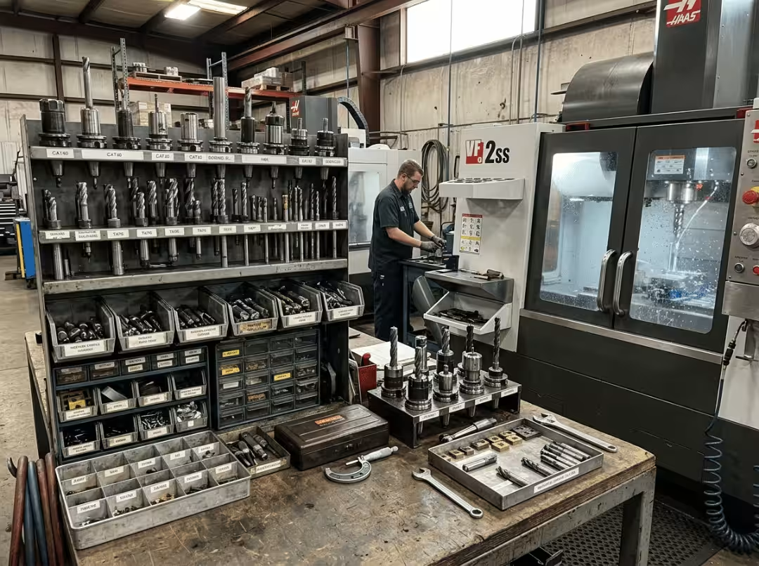
Stand in front of a tool crib long enough, and the options stop looking like choices and start looking like noise. You have a slot to cut, a bore to finish, a thread to form — and a catalog that treats every tool as equally relevant. The question you actually need answered is never “what tools exist.” It’s which one belongs on this job, in this material, running against this tolerance.
Most articles on this subject answer the wrong question. They list the tools, hand you a definition for each, and leave you no better equipped to pick one. You finish knowing that an end mill cuts sideways and a reamer finishes holes, which is not the same thing as knowing when to choose either.
This article is organized around the choice. It gives you a functional framework for classifying tools by what they do, a logic for matching a tool to the operation and material, and the tooling decisions that most reliably produce scrap. Names are easy. Picking well is the skill.
CNC Machine vs CNC Tool — The Distinction That Matters for Cost
The two terms get used interchangeably, and the confusion causes real problems when you’re buying or specifying manufacturing work.
A CNC machine is the full system: base, spindle, motors, controller, axes, and tool holders. It reads code and moves the spindle or workpiece along a programmed path. On its own, it doesn’t remove any material — it provides controlled motion, nothing else.
A CNC tool is the cutter that actually contacts the part: the end mill, drill, turning insert, tap. It converts controlled machine motion into a machined feature. The machine moves; the tool cuts. Neither is useful in the other’s absence.
The distinction matters more for cost than for vocabulary. You buy a machine once and run it for years. Tools are consumables — they wear, chip, and get swapped out constantly. That means tool selection is where most of the real quality and cost decisions happen on a daily basis. A shop with excellent machines can scrap parts all week by loading the wrong cutters. When experienced machinists talk about getting tooling right, this is the layer they mean.
How CNC Machine Tools Are Actually Classified
Sorting tools by name produces a list. Lists are hard to reason from — you end up memorizing entries instead of understanding the relationships between them. Sorting by function does something more useful: it tells you which family of tools a job calls for before you ever pick a specific cutter.
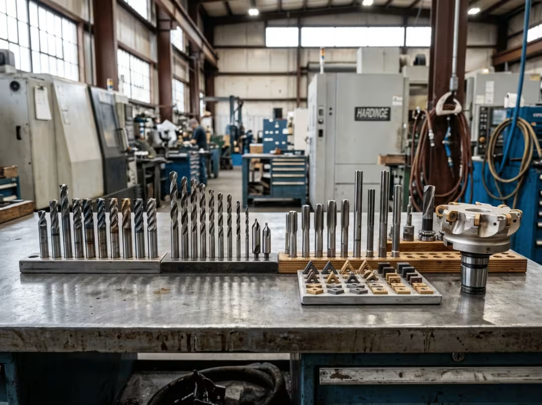
The functional groups worth knowing:
- Material removal (roughing) — clearing bulk stock fast. End mills and face mills carry this load.
- Profiling and contouring — shaping features and surfaces, from a simple outline to a sculpted 3D form. End mills again, but chosen differently.
- Hole-making — creating holes from solid material or opening existing ones. Drills start them; boring bars enlarge them.
- Hole finishing — bringing a drilled hole to its final size and surface quality. Reamers.
- Threading — internal or external threads. Taps and thread mills.
- Turning — shaping rotating parts on a lathe. Turning inserts and parting tools.
- Surfacing — flattening and finishing large faces quickly. Face mills.
|
Functional group |
Typical tools |
What it produces |
|---|---|---|
|
Material removal |
End mills, face mills |
Fast bulk stock removal |
|
Profiling / contouring |
End mills |
Slots, pockets, profiles, 3D surfaces |
|
Hole-making |
Drills, boring bars |
Round holes, enlarged bores |
|
Hole finishing |
Reamers |
Precise, smooth-walled holes |
|
Threading |
Taps, thread mills |
Internal and external threads |
|
Turning |
Turning inserts, parting tools |
Cylindrical features, grooves, cut-offs |
|
Surfacing |
Face mills |
Flat, finished faces |
This framework does something the name list cannot: the function narrows the field to a handful of candidates before you ever look at a catalog page. From there, material, geometry, and finish requirements pick the specific tool. One operation almost always has several viable options — the job tells you the family, and the details resolve which tool within that family.
Common CNC Machine Tools and What Each One Actually Does Best
These tools get searched by name, so here they are — but framed around the decision rather than the definition. For each: what it does, where it earns its place, and where people get it wrong.
End Mills
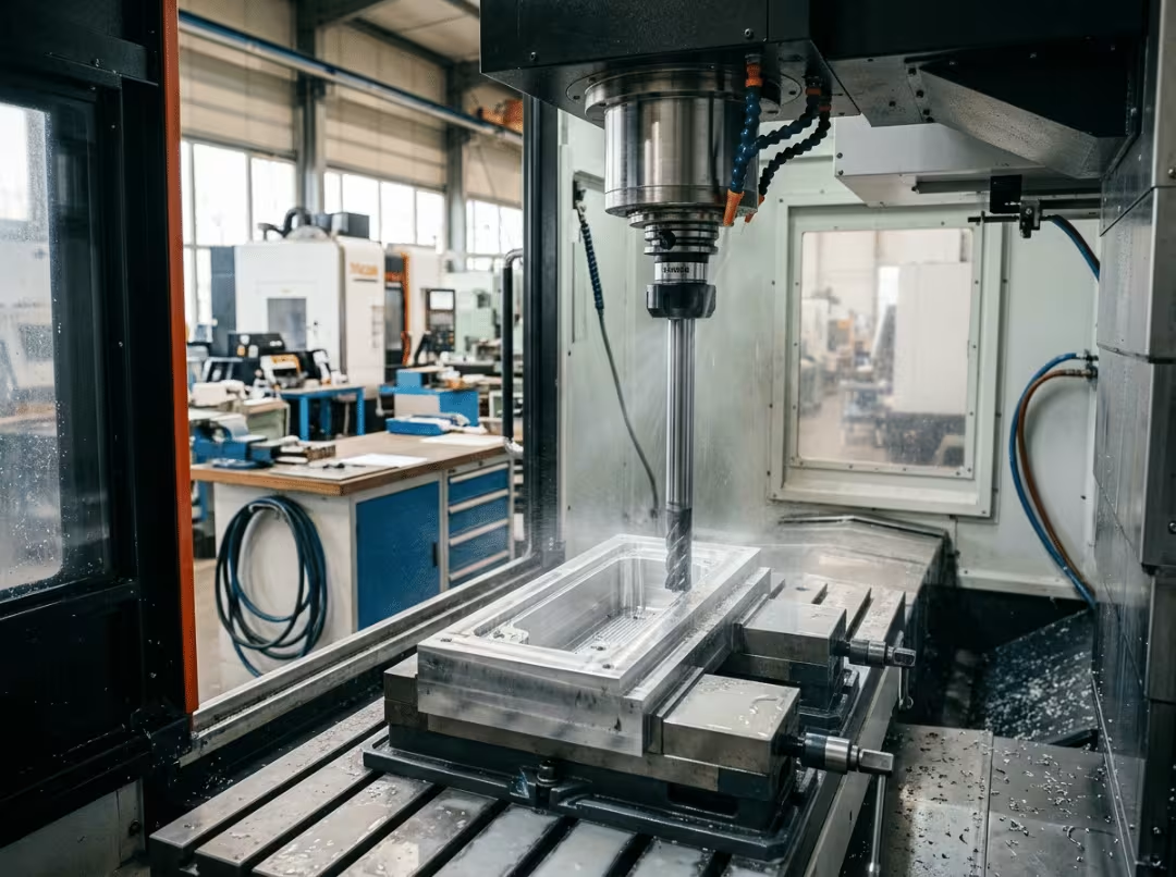
An end mill cuts on both its side and tip, which lets it plunge, slot, profile, and skim 3D surfaces. It’s the most versatile cutter in a milling shop. The practical splits are: flat for square corners and flat-bottomed pockets, ball nose for contours and sculpted surfaces, corner-radius for longer life on deep cuts, and roughing mills for tearing out bulk stock ahead of a finish pass.
Where it goes wrong: too much stick-out. A slender end mill hanging well out of the holder flexes under cutting load. That deflection prints directly into the part — an out-of-spec wall, a tapered pocket, or a finish that doesn’t match the rest of the run.
Drill Bits
Drills make round holes by cutting straight down, sized to the hole diameter. Twist drills handle general work. Center and spot drills put a precise dimple down first so the main drill doesn’t wander. For deep holes, a peck strategy — short passes with regular retractions to clear chips — keeps heat and packing under control.
Where it goes wrong: expecting a drilled hole to hold a tight tolerance. A drill produces a hole that is approximately the right size and approximately round. When the print calls for a precise fit, that requires reaming or boring — not a better drill.
Reamers
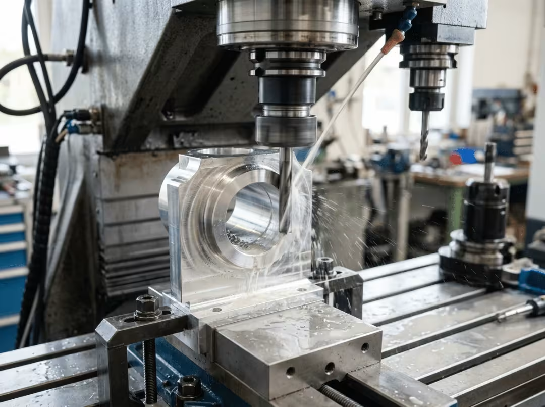
A reamer takes a drilled hole and brings it to its final diameter with a smooth wall, removing only a few thousandths. It is a finishing tool. The point most people miss is the division of labor: the drill makes the hole, the reamer makes it right. Trying to drill straight to a tight tolerance and skip the reamer is a reliable way to get holes that measure differently from part to part.
Taps and Thread Mills
Both cut internal threads. Taps are faster — the standard choice in cooperative materials. Thread mills cut threads with a helical path, which makes them safer in hard or gummy materials and flexible enough to handle different pitches without a tool change.
Where it goes wrong: tapping in material that fights back. A tap that seizes and snaps inside a nearly finished part usually scraps it. In titanium, stainless with work-hardening tendencies, or any material that grips the tap, thread milling is the lower-risk call. The extra cycle time is cheap insurance.
Face Mills
Face mills are broad, multi-insert cutters built to flatten large surfaces in fewer passes. They square up rough blanks, prepare mating surfaces, and clean up stock before welding. When the job calls for a dead-flat plane over a wide area and the part needs it quickly, this is the right tool.
Turning Tools (Lathe Inserts)
Turning tools cut rotating stock on a lathe: external turning to shape the outside diameter, facing to clean up ends, grooving for seal or snap-ring seats, threading for fastener interfaces. Insert geometry and grade do most of the precision work here. The depth on turning tool selection belongs in the material and selection sections — a list of insert shapes is less useful than knowing what drives the choice.
Boring Bars
A boring bar enlarges and finishes an existing hole, delivering better roundness and tighter tolerance than a drill can manage alone. It takes light passes, shaving the bore to final size. The failure mode is chatter: a long, unsupported bar reaching into a deep bore vibrates, and you hear it and see it in the finish. When the depth-to-diameter ratio gets long, a vibration-damping bar solves the problem rather than pushing a standard bar past its usable reach.
Parting (Cut-Off) Tools
Parting tools are thin blades that cross a rotating workpiece to separate finished parts from bar stock. The same geometry cuts grooves. The failure mode is binary: feed too timidly and the blade rubs and chatters until it deflects; feed too aggressively and it breaks. Parting rewards a steady, committed feed rate more than most operations — hesitation causes the failures it’s trying to avoid.
Knowing these names is the starting point. Matching them to the job, in the right material, at the right tolerance, is where the next two sections do their work.
Tool Materials and Coatings — Reading Them as Selection Decisions
Tool material and coating are not background details. They determine how fast you can run, how long the edge lasts, and whether the workpiece fights you throughout the cut. The right way to read them is as choices linked to specific conditions — not as a spec-sheet checklist.
Tool Materials
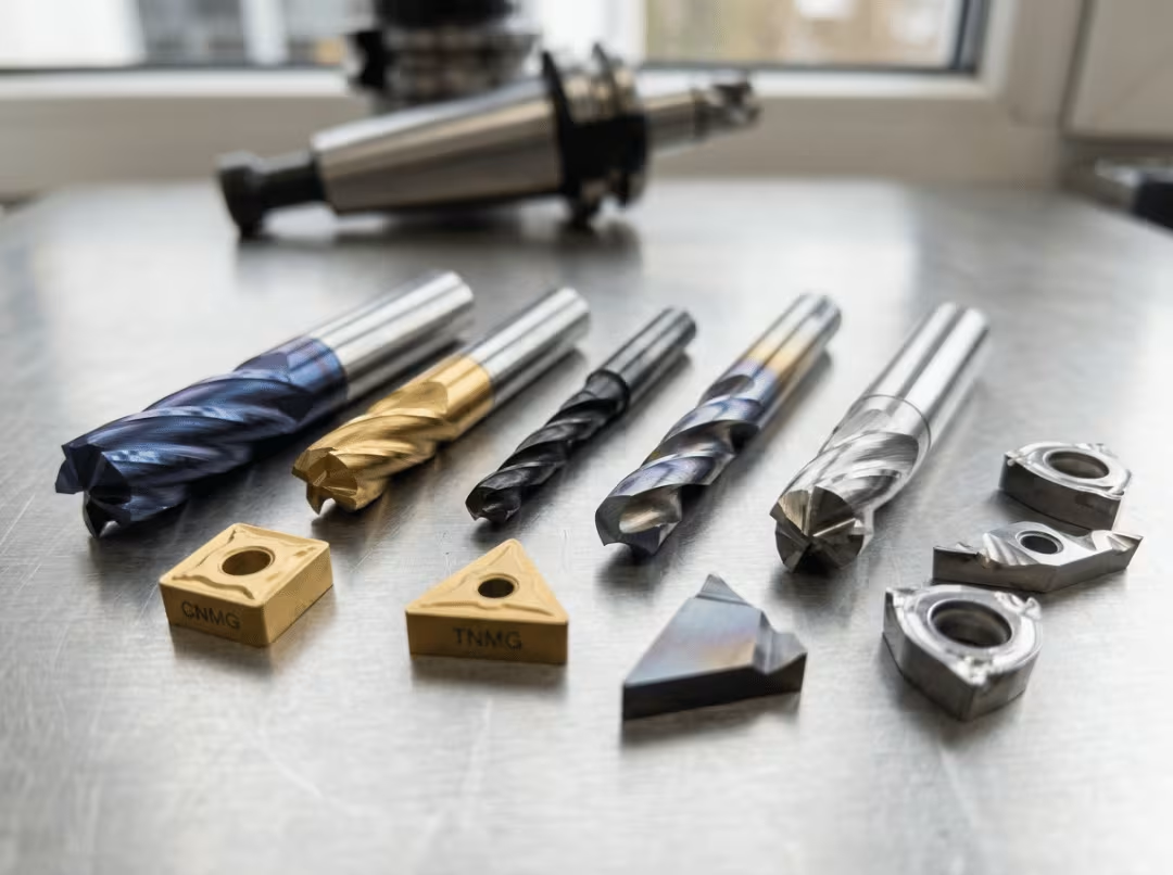
High-speed steel (HSS) is tough, forgiving, and inexpensive. It absorbs shock without chipping, which makes it the right pick for softer materials, low-volume work, and interrupted cuts where a more brittle tool would crack. It won’t run as fast or hold an edge as long as carbide, but it fails predictably and regrindably.
Carbide is harder, tolerates higher temperatures, and holds its edge through far longer runs. It’s the production default for most metalwork. The trade-off is brittleness: a sudden shock load or a poorly managed interrupted cut can chip it in ways HSS would simply shrug off.
Ceramic and cermet handle the heat and speed that would exhaust carbide on hard materials. They’re fragile — stable, continuous cuts only. Not for interrupted work, thin walls, or situations with any real shock.
Diamond-tipped (PCD) is for abrasive non-ferrous materials and composites: high-silicon aluminum, carbon fiber layups, reinforced plastics. Never use it on steel. The chemistry between diamond and iron destroys the edge.
|
Tool material |
Where it fits |
Trade-off |
|---|---|---|
|
HSS |
Soft metals, low volume, interrupted cuts |
Slower, shorter edge life |
|
Carbide |
Most metals, production runs |
More brittle, higher cost |
|
Ceramic / cermet |
Hard material at high speed |
Fragile; needs stable, continuous cuts |
|
PCD (diamond) |
Abrasive non-ferrous, composites |
Cannot cut ferrous metals |
Coatings
A coating manages heat and wear. It is not a performance sticker that rescues a tool chosen incorrectly for the job.
TiN (titanium nitride) adds modest hardness and wear resistance on mid-speed work in ordinary materials — general-purpose life extension.
TiAlN / AlTiN handles heat. Choose it for stainless and titanium, for dry machining, or any high-speed cut where the edge would otherwise overheat and break down prematurely.
DLC (diamond-like carbon) is slick and low-friction, which prevents soft material from welding to the cutting edge. It’s the right call for aluminum, copper, and plastics, where built-up edge otherwise wrecks finish and dimensional control.
The point that gets missed: a coating will not fix the wrong substrate or a tool that’s failing from deflection. Substrate and geometry come first. The coating optimizes a decision that’s already correct — it doesn’t correct one that isn’t.
How to Choose the Right CNC Machine Tool
Everything above feeds into a repeatable five-step sequence. Work through it in order on any part and the field narrows to a defensible short list before you reach step five.
1. Start with the Operation
The operation places you in one of the functional groups from earlier, which eliminates most of the catalog immediately. Cutting a slot or pocket: end mill. Making a hole: drill. Holding that hole to a tight tolerance: add a reaming or boring step. Forming a thread: tap or thread mill. Shaping a rotating part: turning tool. One question, answered honestly, goes from three hundred options to a handful.
2. Match the Tool to the Material
Material sets the substrate and coating. Aluminum wants sharp geometry and a low-friction coating like DLC to prevent built-up edge. Stainless wants a heat-managing coating — TiAlN — and controlled engagement per pass to avoid work-hardening the surface. Hard steel pushes you toward carbide, then ceramic; past a certain hardness, toward a different process altogether, like grinding or EDM. Get the material read wrong and even the right tool family underperforms.
3. Factor in Geometry and Access
The part’s shape now constrains what’s physically possible. Deep pockets, thin walls, and awkward reach all affect tool length, diameter, and the rigidity you can achieve. The trade-off that catches people most often: the longest tool that reaches the feature is rarely the one that holds tolerance. Every added millimeter of stick-out introduces flex, and flex becomes dimensional error in the finished part. Use the shortest, stiffest tool that can still reach — not the longest one that can.
4. Set Tolerance and Finish Honestly
Tolerance and finish requirements determine whether a cutting operation is sufficient or whether a finishing step is needed behind it. A drilled hole won’t hold a press fit — if the print is tight, a reaming or boring pass is not optional. A milled surface may need a separate finishing pass to reach the required Ra. Specifying what the function actually demands, rather than what seems safe or standard, keeps unnecessary tools and steps out of the process.
5. Factor in Production Volume
One part and ten thousand parts call for different tool decisions on identical geometry. For a prototype, general-purpose HSS tooling is often the sensible choice — there’s nothing to amortize. For a production run, carbide with the right coating pays back its cost in shorter cycle times and far longer edge life. The economics flip at volume, and the tooling choice should flip with them.
These variables interact. A tight tolerance in a deep pocket in hard steel at volume is a completely different problem from a shallow slot in aluminum for a one-off. Reading all five together is the actual skill — picking one variable in isolation usually produces the wrong answer. When those trade-offs are worth resolving before machining starts, a DFM review through Essengold’s CNC machining services works through this sequence against your specific part.
Common CNC Tooling Mistakes That Cause Scrap and Cost
Most scrapped parts don’t originate at the machine. They originate at the planning stage, in a tool choice made before the spindle turned. These are the decisions that show up most consistently in scrap bins.
Too much stick-out. A tool hanging far out of the holder flexes under cutting load. That deflection ends up in the part — a tapered wall, an oversized pocket, a feature that measures correctly in CAD and incorrectly on the floor. The fix is straightforward: use the shortest tool that reaches the feature, and seat it as deep in the holder as the geometry allows.
Treating a drilled hole as a precision hole. A drill produces a hole that’s approximately the right diameter and approximately round. “Approximately” is acceptable for a clearance hole. For a bearing seat, a press fit, or a hydraulic valve bore, it isn’t. Add a reaming or boring step for any hole the function actually depends on.
Wrong substrate for the workpiece and cut type. HSS running in hard steel at production feeds wears out mid-run and drifts your dimensions. Carbide loaded into a heavy interrupted cut without the geometry to handle shock chips instead. The fix is matching the substrate to both the material hardness and the nature of the engagement — stable continuous cut or interrupted, high-feed cut — before the tool goes in the holder.
Coating-first thinking. A coating on a tool that’s failing from deflection or wrong geometry changes nothing useful. TiAlN on a tool that’s chattering, DLC on a job that isn’t building up material — money spent on the wrong problem. The substrate and geometry solve the problem. The coating then optimizes a correct solution.
Ignoring chip evacuation. Chips that don’t clear get recut. Recut chips raise heat, ruin finish, and snap tools — particularly in deep pockets and blind holes. Peck cycles for deep drilling, directed coolant or air, and flute geometry that lifts chips out rather than packing them in are the levers to pull.
Timid parting feeds. A parting blade fed too lightly rubs instead of cutting. The heat builds, chatter starts, and the blade deflects or breaks. The fix is a steady, committed feed rate — not aggressive, not hesitant. Parting is one operation where the instinct to go slowly causes exactly the failure people are trying to prevent.
These are decisions, not accidents. Each one was made — or skipped — before the machine ran. Each one is preventable at the planning stage.
How Tooling Choices Land in the Finished Part
Tooling decisions don’t stay abstract — they show up in the dimensional accuracy, surface finish, and scrap rate of the parts you ship. The same feature can pass or fail depending on which tool cut it.
In milling, end mill and face mill choices determine finish and feature accuracy on prismatic parts — housings, brackets, manifold bodies. The wrong flute count or too much stick-out shows up as chatter marks or an out-of-tolerance wall. Getting this right consistently is what allows Essengold’s CNC milling service to hold close tolerances across everything from simple flat plates to complex multi-face components.
In turning, insert grade and nose geometry drive roundness and surface finish directly on rotational parts. A grade suited to the material and a nose radius matched to the required finish are the difference between a shaft that seals reliably and one that doesn’t. That tooling discipline is what Essengold’s CNC turning service applies to shafts, fittings, and precision turned components.
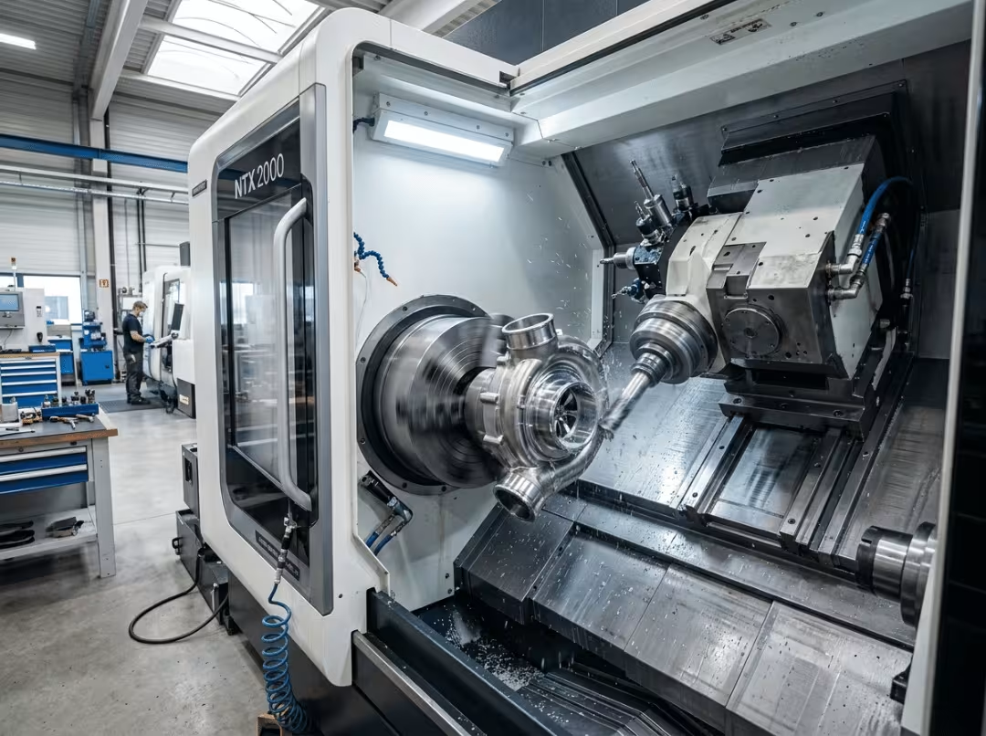
In turn-mill work, coordinating turning and milling tooling in a single setup eliminates the fixture-to-fixture alignment error that accumulates when a part moves between separate machines. That is exactly what Essengold’s millturn machining is built to manage on parts where turned and prismatic features have to relate precisely to each other.
The practical conclusion: tooling belongs in the design and DFM conversation, not in the post-quote discussion about why the part came back wrong.
CNC Machine Tools — FAQ
What is the difference between a CNC machine and a CNC tool?
The machine is the complete system — base, spindle, controller, axes — that provides controlled motion. The tool is the cutter that contacts the workpiece and removes material. The machine positions and moves; the tool cuts. Neither produces a part without the other.
What are the main types of CNC machine tools?
Grouped by function: material removal (end mills, face mills), hole-making (drills, boring bars), hole finishing (reamers), threading (taps, thread mills), turning (inserts, parting tools), and surfacing (face mills). The functional grouping tells you which family a job calls for before you look at individual tools.
What are CNC cutting tools made from?
Primarily HSS, carbide, ceramic or cermet, and PCD. HSS is tough and economical for softer materials and low volume. Carbide is the production default for most metals. Ceramic handles hard material at high cutting speed. PCD is for abrasive non-ferrous materials and composites — it will not work on steel.
What is the difference between drilling and reaming?
Drilling creates the hole; reaming finishes it. A drill brings the hole to approximately the right size and shape. A reamer removes a few thousandths to reach the exact diameter with a smooth, accurate wall. Precision fits require both steps.
When should I use carbide instead of HSS?
Use carbide for harder materials, higher cutting speeds, production volume, and applications where surface finish matters. HSS fits softer materials, low-volume or prototype work, and interrupted cuts where its toughness resists the chipping that carbide can suffer under shock loading.
Do tool coatings actually matter?
Yes — but only on a tool that’s already correct for the job. Coatings manage heat and wear: TiAlN for heat-intensive cutting in stainless and titanium, DLC for aluminum and other non-ferrous materials that build up on the edge. A coating will not recover a wrong substrate or fix a tool failing from deflection.
How do I choose the right CNC tool for my part?
Work through five variables in order: operation (which functional group), material (substrate and coating), geometry and access (tool length and rigidity), tolerance and finish (whether a finishing step is needed), then production volume (HSS versus carbide, general versus specialized). Reading all five together resolves the choice; picking one in isolation usually doesn’t.
Choosing Tools, Not Memorizing Them
CNC machine tools are a set of decisions, not a catalog entry. The tool follows the operation, then the material, then the geometry, then the tolerance and finish, then the volume. Run that sequence consistently and a full tool crib collapses to a short, defensible list on any given job.
The functional classification tells you which family to look in. The five-variable sequence tells you which tool in that family will actually hold up. The common mistakes — stick-out, skipped finishing steps, wrong substrate, ignored chip evacuation — are all decisions made before the machine runs, which means they’re all catchable before any metal is cut.
For teams that would rather hand those decisions to a shop that works through them daily, Essengold covers milling, turning, and millturn work across metals and engineering plastics. Submit your design files for a DFM review and you’ll get a direct assessment of the process and tooling — the sequence above, run against your part before anything gets cut.