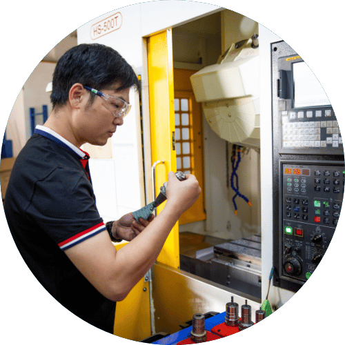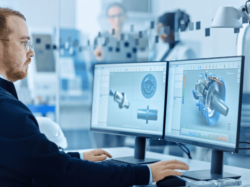
CNC machines, which employ computer numerical control, are among the most precise and popular machining tools available today. They use computer programs such as CAD and CAM to manufacture components without human intervention.
The CNC cutting tools are moved in response to CAD models and CAM toolpaths, which are essential computer instructions in the manufacturing process. Since each machine’s specifications are unique, developing and deploying these programs can be challenging even for an accomplished CNC programmer. However, the fundamentals are easier to grasp than you may imagine and generally follow common practice among experts.
To help you get started with CNC machining, this article will introduce you to CAD and CAM. By the time you finish this read, you’ll know how to utilize basic design and manufacturing software to make your components.
The Basics of CAD and CAM
What is CAD: The Master of Design?
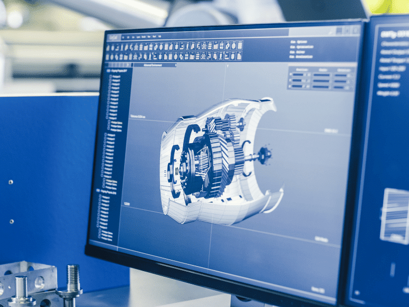
The most widely used software for designing parts for CNC machines is CAD (Computer-Aided Design). Since CAD serves as the foundation for modern manufacturing, most engineering processes begin with this tool. When producing a component, machinists are guided by CAD models that specify its exact dimensions, geometric tolerances, and structural features.
However, engineers may find CAD modeling challenging because different industries have varying requirements for design formatting. Most models differ only in the number of complex surfaces used and the number of precise constraints placed between lines and arcs. A designer may utilize 2D drafting, whereas another may choose 3D modeling. Machinists should constantly be well-versed in the technology they are operating. If the design is wrong, the component’s manufacturing might be severely disrupted.
While 3D modeling is the most common feature in CAD software, other tools offer different capabilities depending on the software’s complexity.
What is CAM: The Organizer of Manufacturing?
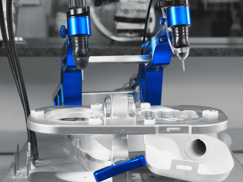
CAM (Computer-Aided Manufacturing) software regulates a wide variety of machine operations based on the digital model. Some of these functions include toolpath generation, cutting speed optimization, and spindle rotation calculation. The precise machine may have slight variations in how it interprets these functions.
When configuring the CNC manufacturing program with CAD and CAM, keep in mind that each CAM operation should only focus on a specific machining step. The reason is that their major function is to guide the device safely and accurately. This means that using improper toolpaths more than once within the same block can lead to unexpected behavior during physical machining.
Even while each design software has its own unique set of tools, CAM programs are likewise machine-specific. The specific cutting strategies used in some software may be skipped on some machines but not on others.
How CAD and CAM Differ
Machinists employ both CAD and CAM in every CNC machining process, although each serves a different purpose. Some ways in which they differ are highlighted below:
Most CAD programs focus strictly on the visual and geometric representation of a part, whereas CAM systems tend to emphasize practical manufacturing steps. To conceptualize the component’s shape and dimensions, CAD tools are used, whereas CAM tools control the machine’s external physical motions during the operation.
While the CAD software initiates the creative and engineering phases of the project, the CAM software initiates the production logic, generating the code that the CNC machine will read and execute.
Programming CNC with CAD and CAM
There are distinct steps that must be implemented in CNC programs when using these software tools. For instance, the initial phase involves using CAD software to create a comprehensive digital design. The designer meticulously inputs all necessary dimensions and features to construct a highly accurate 3D model of the workpiece. Similarly, this step allows the engineer to simulate stress tests and ensure the part is structurally sound before production.
Let’s say you want to manufacture that part using a CNC machine; this example will help you see how to use CAM to generate machine instructions. Simply import the completed CAD model into your CAM software. The CAM system analyzes the geometry and automatically generates the necessary toolpaths, calculating the most efficient routes for the cutting tools at a specific feed rate. It translates the visual model into actionable manufacturing data.
Say you need your machine to execute complex multi-axis movements with high precision. For this, you rely heavily on how CAD and CAM software simplify the overall CNC programming process. Always remember that the CNC milling machine’s spindle won’t start turning until the CAM software has successfully converted the CAD design into a flawless set of machine-readable codes.
Examples of CAD and CAM Software
Modern machines and programs allow machine operators to simply provide digital files to the system. The machine-readable toolpaths and codes will be generated by the software. Coding machine operations has become a breeze with the help of industry-leading CAD and CAM programs.
To get started, the programmer requires sophisticated computer-aided design (CAD) software such as AutoCAD or SolidWorks. Following this, the programmer imports the part model into CAM software such as Mastercam or Fusion 360. He or she may also decide which tools to use and which pathways the spindle will take when cutting. The necessary instructions for the machine’s operation are then generated by the software.
In this part, we’ll look at several instances to better understand the fundamental CAD and CAM software available today.
| Software Name | Primary Function |
|---|---|
| AutoCAD | 2D Drafting and Basic 3D Modeling |
| SolidWorks | Advanced 3D Parametric Modeling |
| CATIA | Advanced Surface Modeling |
| NX CAD | Integrated Product Design |
| Creo | Scalable 3D CAD Software |
| Rhino | Freeform Surface Modeler |
| Inventor | Mechanical Design and Simulation |
| Solid Edge | Direct Modeling Design |
| SketchUp | Intuitive 3D Concepting |
| DraftSight | Professional 2D Drafting |
| Software Name | Primary Function |
|---|---|
| Onshape | Cloud-Based Product Design |
| FreeCAD | Open-Source Parametric Modeler |
| Tinkercad | Entry-Level 3D Design |
| MicroStation | Infrastructure Design |
| ZBrush | Digital Sculpting |
| Blender | 3D Creation Suite |
| BricsCAD | AI-Driven Drafting Software |
| IronCAD | Dynamic 3D Modeling |
| Software Name | Primary Function |
|---|---|
| Mastercam | Advanced Milling Toolpaths |
| Fusion 360 | Integrated CAD/CAM Cloud Platform |
| GibbsCAM | Production Milling Automation |
| SolidCAM | Seamless SolidWorks Integration |
| EdgeCAM | Intelligent Machining Operations |
| HyperMill | 5-Axis Milling Solutions |
| PowerMill | High-Speed Machining Programming |
| Surfcam | TrueMill Toolpath Technology |
| SprutCAM | Streamlined CNC Programming |
| Software Name | Primary Function |
|---|---|
| Mastercam Lathe | Comprehensive Turning Operations |
| Fusion 360 Turning | Cloud-Based Lathe Programming |
| GibbsCAM Turning | Multi-Task Machining |
| SolidCAM Turning | Advanced Mill-Turn Integration |
| EdgeCAM Turning | Optimized Lathe Toolpaths |
| PartMaker | Swiss-Type Lathe Programming |
| Esprit | High-Performance Turning |
| Cimatron | Manufacturing Software Solutions |
| CamWorks | Feature-Based Machining |
Benefits of Using CAD and CAM in CNC Machining
To get the most out of modern manufacturing, adopting CAD and CAM systems is essential. These programs offer unmatched precision, ensuring that every manufactured part matches the original design down to the smallest micrometer. The automation provided by these software tools significantly boosts overall efficiency, allowing machine shops to produce complex components much faster and with far fewer errors than traditional methods.
This is a brief overview of how CAD and CAM programs direct the actions of CNC machines. Although the steps outlined above may seem easy enough, mastering the software for a complex component can take time. Ultimately, the integration of CAD and CAM minimizes material waste and ensures consistent, repeatable quality.
Conclusion
CNC machining relies heavily on CNC machines. Nevertheless, without CAD and CAM software, which tell machines exactly what to do, they would not be able to perform their jobs efficiently. It is crucial to the CNC machining process and the effective manufacturing of components that you understand how to utilize these integrated systems. Knowing how to leverage CAD and CAM tools will put you ahead of the competition in the competitive field of CNC programming.
Turn to Essengold for CNC Machining Services
But only knowing the basics of CNC programming with CAD and CAM is far from enough. Working with a machine shop (or machinist) that is knowledgeable about geometric precision and advanced computer-aided manufacturing (CAM) will greatly contribute to the success of your machining project. Need a machine shop (or machinist) to handle your CNC machining project?
Essengold is a leading manufacturer offering excellent CNC machining services. With us, you’ll get the premium services you crave at an affordable price with incredibly good quality. Our team of expert CNC machinists, engineers, and programmers can review your 3D CAD model and accurately manufacture your parts using advanced CAM programming and CNC machining.