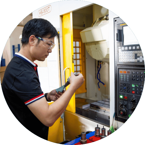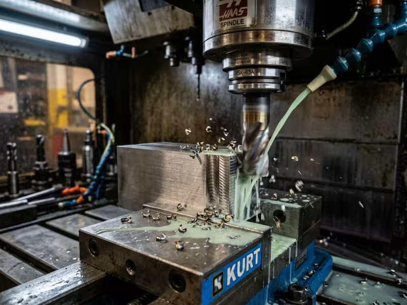
A new programmer ran a 1/2″ carbide end mill in 304 stainless at 6,000 RPM. The corners glowed red and burned off in under two minutes.
Cutting speed is how fast the cutting edge moves across the workpiece surface. Feed rate is how far the tool advances into the material, per revolution, per tooth, or per minute.
Together, these two numbers decide your tool life, surface finish, and how many parts you ship per shift.
I set speeds and feeds on CNC jobs every week. This article covers how they differ, how they connect, the formulas behind them, and step-by-step calculations with worked examples.
What Cutting Speed and Feed Rate Really Mean
Speed and feed often sit side by side on the same chart. But they measure two different motions. If you mix them up, every number you calculate after that will be wrong.
Cutting speed (Vc) is how fast the cutting edge travels across the workpiece surface. Imperial shops measure it in surface feet per minute (SFM). Metric shops use meters per minute (m/min).
In CNC turning, the part’s surface spins past a fixed tool. In milling and drilling, the tool’s outer edge sweeps past a fixed part. Either way, Vc describes the speed at the point where metal meets edge.
RPM is related to cutting speed, but it isn’t cutting speed. RPM only counts spindle turns per minute. Cutting speed depends on RPM and diameter.
Here’s an example. At 1,000 RPM, the surface of a 1″ bar moves at about 262 SFM. A 4″ bar at the same RPM moves at about 1,047 SFM, four times faster. That’s why tool catalogs list speeds in SFM or m/min, not RPM. You convert to RPM for each diameter you cut.
Feed rate is how far the tool advances into the material. Shops express it in two ways:
- Per revolution: inches per revolution (IPR) or mm/rev. Lathes and drills use this form.
- Per minute: inches per minute (IPM) or mm/min. Mill table feeds use this form.
The operation decides which starting value you look up.
- Turning uses feed per revolution (fn). One insert cuts on every turn, so fn tells you how far the tool moves along the part each revolution.
- Milling uses feed per tooth (fz). An end mill has several flutes, and each one takes its own bite. You multiply fz by the number of flutes and the RPM to get the table feed.
That bite leads to the number I watch most closely: chip load. Chip load is the thickness of material each cutting edge removes. In milling, it equals feed per tooth. In turning, it tracks feed per revolution.
Every insert and end mill works inside a chip load window. If you go too thin, the edge rubs and heats up. If you go too thick, the edge chips or breaks.
Feed Rate vs Cutting Speed: The Real Difference
Both numbers change the cut, but they don’t hurt the same things. Speed mostly attacks the tool. Feed mostly shapes the chip, the cutting force, and the surface. Once you know which one does what, you can troubleshoot much faster.
Start with the number that decides how long your edge lives.
Speed Controls Heat, and Heat Controls Tool Life
A faster cutting speed creates more friction at the edge. It also gives the tool less time to shed that heat.
The effect isn’t linear. With carbide in steel, a 20% speed increase can cut tool life roughly in half. Feed and depth of cut have far less effect on tool life.
Speed set too high shows up as:
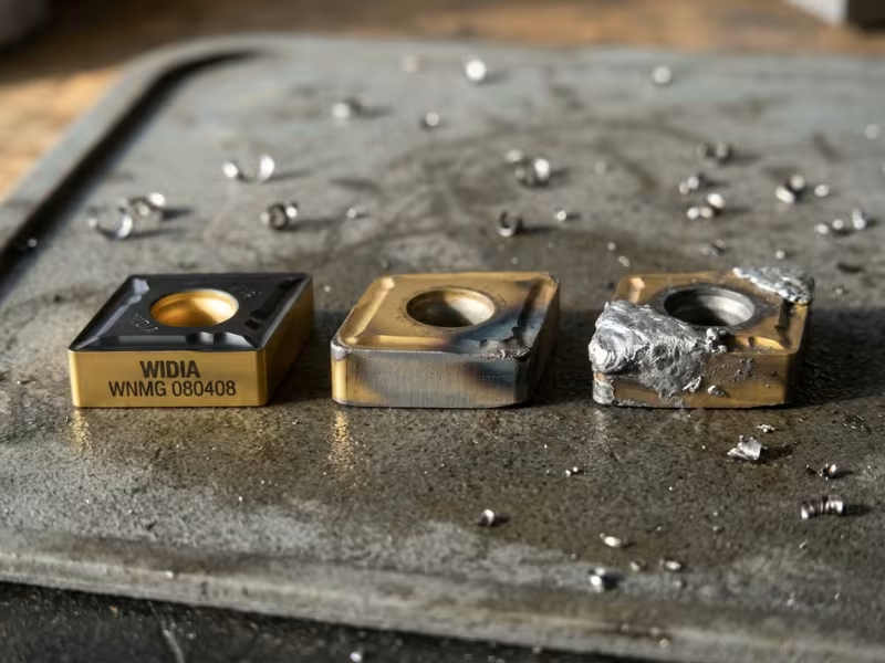
- Fast flank wear or cratering on the insert
- Dark blue or purple chips in steel
- Burned corners on end mills
- A finish that gets worse partway through the batch
Speed set too low brings different problems. Aluminum and soft steel weld to the edge and form a built-up edge, which tears the surface. You also waste cycle time on every part.
Feed works on a different part of the cut.
Feed Controls the Chip, the Force, and the Finish
Feed sets chip thickness. A thicker chip pushes harder on the edge, the tool, and the part.
Feed set too high chips edges, spikes spindle load, and bends tools away from the cut. It also roughens the finish fast. In turning, surface roughness grows with the square of the feed. Double the feed, and the feed marks get about four times deeper.
Feed set too low causes rubbing instead of cutting. In 304 and 316 stainless, that rubbing work-hardens the surface. The next pass then hits a harder layer and wears the edge faster. Light feeds also stop the chipbreaker from working, so chips come off long and stringy.
In stainless, a feed that’s too light often kills tools faster than one that’s slightly too heavy.
So when a cut goes wrong, the symptom tells you where to look.
Which One Should You Change First?
I read the symptom before I touch any number:
|
What you see |
Change first |
|---|---|
|
Fast edge wear, discolored chips, burned corners |
Lower speed 10–15% |
|
Built-up edge on the insert |
Raise speed |
|
Chipped edges, high spindle load, deflection |
Lower feed |
|
Rubbing, glazed surface, stringy chips |
Raise feed |
|
Deep, regular feed marks |
Lower feed |
Change one parameter at a time, in steps of about 10%. Then you know exactly which change fixed the cut.
When the tool looks healthy and I want more output, I raise feed first. Feed adds metal removal without the heat penalty that speed carries.
How Cutting Speed, RPM, and Feed Rate Connect
Speed and feed don’t work alone. They link through one chain: cutting speed sets RPM, and RPM sets feed rate. Follow that order, and the math takes about a minute.
I always start with cutting speed. The tool catalog lists it, and it protects tool life.
Step One: Turn Cutting Speed Into RPM
Your machine can’t run SFM or m/min. It only understands RPM. So you convert, using the diameter at the cut. That’s the bar diameter in turning and the tool diameter in milling and drilling.
- Metric: RPM = (Vc × 1000) ÷ (π × D), with D in mm
- Imperial: RPM = (SFM × 12) ÷ (π × D), with D in inches
The 1000 converts meters to millimeters. The 12 converts feet to inches. Many machinists shorten the imperial version to RPM ≈ (SFM × 3.82) ÷ D.
Here’s a quick check. At 300 SFM, a 1″ bar needs about 1,146 RPM. A 0.5″ end mill at the same speed needs about 2,292 RPM. A smaller diameter always needs more RPM to hold the same surface speed.
Once you know the RPM, feed follows.
Step Two: Turn Chip Load Into Feed Rate
Feed starts as a chip load from the catalog. RPM turns that chip load into motion the control can run.
- Turning: feed per minute = fn × RPM
- Milling: feed rate = fz × z × N
In milling, z is the number of flutes and N is the RPM. Take that 0.5″ four-flute end mill at 0.002″ per tooth and 2,292 RPM. The math gives 0.002 × 4 × 2,292 ≈ 18.3 IPM.
Here’s how the two operations compare:
|
Turning |
Milling |
|
|---|---|---|
|
Diameter in RPM formula |
Workpiece |
Tool |
|
Starting feed value |
fn (IPR or mm/rev) |
fz (in or mm per tooth) |
|
Feed formula |
fn × RPM |
fz × z × N |
|
Usual control mode |
Per revolution (G95) |
Per minute (G94) |
Why the Order Matters
Always work in this order: pick Vc → calculate RPM → calculate feed.
If you change RPM, the feed must change with it. Say chatter forces you to drop the spindle 20% on that end mill. If you keep 18.3 IPM, each tooth now takes a chip about 25% thicker. That’s often enough to chip a corner.
Lathes running in G95 handle this for you. The control multiplies fn by the actual RPM. Mills in G94 don’t, so you need to recalculate the feed every time you touch the spindle speed.
How to Calculate Both Step by Step
Formulas make more sense once you run real numbers through them. Below are two jobs I set up often: a turned steel shaft and a milled aluminum pocket. Each one follows the same order: Vc → RPM → feed.
Let’s start on the lathe.
Turning Example: 2″ Mild Steel Bar
You need to rough a 2″ diameter 1018 steel bar with a coated carbide insert. The insert box recommends about 400 SFM.
Step 1: Start with cutting speed.
Vc = 400 SFM
Step 2: Calculate RPM.
RPM = (SFM × 12) ÷ (π × D)
RPM = (400 × 12) ÷ (3.1416 × 2)
RPM = 4,800 ÷ 6.283 = 764 RPM
I round down to 760 RPM. Rounding down keeps you slightly under the target speed. That protects the edge, and your actual speed still lands near 398 SFM.
Step 3: Choose feed per revolution.
For roughing mild steel with a general-purpose insert, I start at 0.010 IPR. That sits in the middle of most chipbreaker windows. For finishing, I drop to about 0.004–0.006 IPR.
Step 4: Calculate feed per minute.
Feed (IPM) = fn × RPM
Feed = 0.010 × 760 = 7.6 IPM
With a 0.080″ depth of cut per side, the tool travels 7.6″ along the bar each minute.
As the diameter shrinks, the surface speed drops at fixed RPM. Most CNC lathes fix this with constant surface speed (G96). Always set a max RPM limit with it, such as G50 S3000 on Fanuc-style controls. Without that cap, the spindle can overspeed as the tool nears the center.
Now the same logic moves to the mill.

Milling Example: 12 mm End Mill in Aluminum
Pocketing is everyday CNC milling work. Here, you need to cut a pocket in 6061 aluminum with a 12 mm, 4-flute carbide end mill. On a lighter machine, I start at a conservative 150 m/min.
Step 1: Start with cutting speed.
Vc = 150 m/min
Step 2: Calculate RPM.
RPM = (Vc × 1000) ÷ (π × D)
RPM = (150 × 1000) ÷ (3.1416 × 12)
RPM = 150,000 ÷ 37.70 = 3,979 RPM
I round down to 3,950 RPM. That puts the actual cutting speed at about 149 m/min.
Step 3: Choose chip load.
fz = 0.05 mm per tooth
That’s a safe opening value for a 12 mm cutter. Aluminum can often take 0.08–0.10 mm once the cut proves stable.
Step 4: Calculate table feed.
Feed (mm/min) = fz × z × N
Feed = 0.05 × 4 × 3,950 = 790 mm/min
Always calculate feed from the rounded RPM, not the raw number. If you use 3,979 RPM and then run at 3,950, your chip load drifts.
I’d run this at 6 mm axial depth and 3 mm radial engagement (25%). If the cut sounds clean and the chips come off as small, shiny curls, raise fz in 10% steps.
With both jobs worked out, here’s the full picture on one sheet.
Quick Recap Table
|
Parameter |
Turning job |
Milling job |
|---|---|---|
|
Material |
1018 mild steel |
6061 aluminum |
|
Tool |
Coated carbide insert |
12 mm 4-flute carbide end mill |
|
Diameter used in RPM formula |
2″ (workpiece) |
12 mm (tool) |
|
Cutting speed (Vc) |
400 SFM |
150 m/min |
|
Calculated RPM |
764 |
3,979 |
|
Programmed RPM (rounded down) |
760 |
3,950 |
|
Feed value |
fn = 0.010 IPR |
fz = 0.05 mm/tooth |
|
Feed rate |
7.6 IPM |
790 mm/min |
|
Depth of cut |
0.080″ per side |
6 mm axial, 3 mm radial |
Copy these numbers into your setup sheet as a starting point. Then let the first part confirm them. Watch the chips, listen to the cut, and check the spindle load before you push any value higher.
Starting Values by Material and Operation
Every job needs a first number to run, and this table gives you one. These are the values I start with on a rigid CNC machine. Most rows assume carbide tools, and one HSS row shows how far the numbers drop. Treat them as safe opening values, not limits.
Milling feeds assume a 1/4″–1/2″ (6–12 mm) end mill. Turning feeds assume a general-purpose insert.
|
Material |
Tool type |
Starting cutting speed (SFM / m/min) |
Starting feed guidance |
Caution note |
|---|---|---|---|---|
|
Aluminum 6061 |
Uncoated or polished carbide |
500–1,500 / 150–450 |
Turning: 0.006–0.015 IPR · Milling: 0.002–0.005″/tooth |
Clear chips fast, or they weld to the flutes |
|
Mild steel 1018 |
Coated carbide |
350–700 / 110–210 |
Turning: 0.008–0.015 IPR · Milling: 0.002–0.004″/tooth |
Watch chip color. Dark blue means too fast |
|
Mild steel 1018 |
HSS |
80–120 / 25–35 |
Turning: 0.005–0.010 IPR · Milling: 0.001–0.003″/tooth |
Use flood coolant to protect the edge |
|
Stainless 304/316 |
Coated carbide |
250–500 / 75–150 |
Turning: 0.006–0.012 IPR · Milling: 0.0015–0.003″/tooth |
Never feed light. Rubbing work-hardens the surface |
|
Titanium Ti-6Al-4V |
Coated carbide |
150–250 / 45–75 |
Turning: 0.004–0.008 IPR · Milling: 0.001–0.003″/tooth |
Keep speed low and coolant heavy |
|
Engineering plastics (POM, nylon) |
Sharp uncoated carbide |
500–1,000 / 150–300 |
Turning: 0.005–0.012 IPR · Milling: 0.003–0.008″/tooth |
Light feeds melt the chip. Keep the edge sharp |
Across everyday CNC metal machining, speed ranges shrink fast as materials get tougher. At the top of its range, aluminum runs about five times faster than titanium. Each step down the table leaves you less room for error.
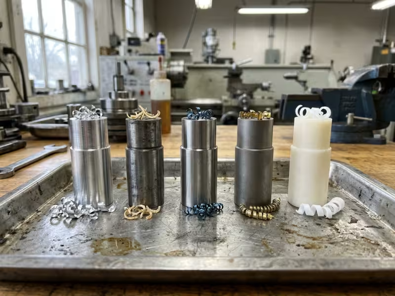
HSS or Carbide?
Tool material shifts these numbers more than most people expect. HSS runs at roughly one-quarter to one-third of carbide speeds. It also needs lighter feeds.
HSS still has a place. It works for small drills, form tools, and older machines that can’t reach high RPM. For production work, carbide wins on speed and tool life.
The Catalog Beats Any Chart
Your toolmaker’s data always comes first. Read the insert box or the end mill catalog before you use any generic range, including this one.
The toolmaker tested that exact grade, coating, and chipbreaker together. If the box says 300–450 SFM and this table says 350–700, run 300–450.
From there, adjust for your setup:
- Long overhang or light machine: start at the low end of the range.
- Interrupted cuts: drop speed about 10–20% to protect the edge from impact.
- Roughing vs finishing: run roughing passes at the middle of the feed range. Finishing passes usually need more speed and less feed.
Write down every value that works. A tested number from your own machine is worth more than any chart.
Practical Adjustments on the Machine
Your calculations get you to the first cut. After that, the machine tells you what to change. I run the first part at about 80% of the planned feed and let the cut report back.
Start by reading what the cut shows you.
Read the Chips, the Sound, and the Surface
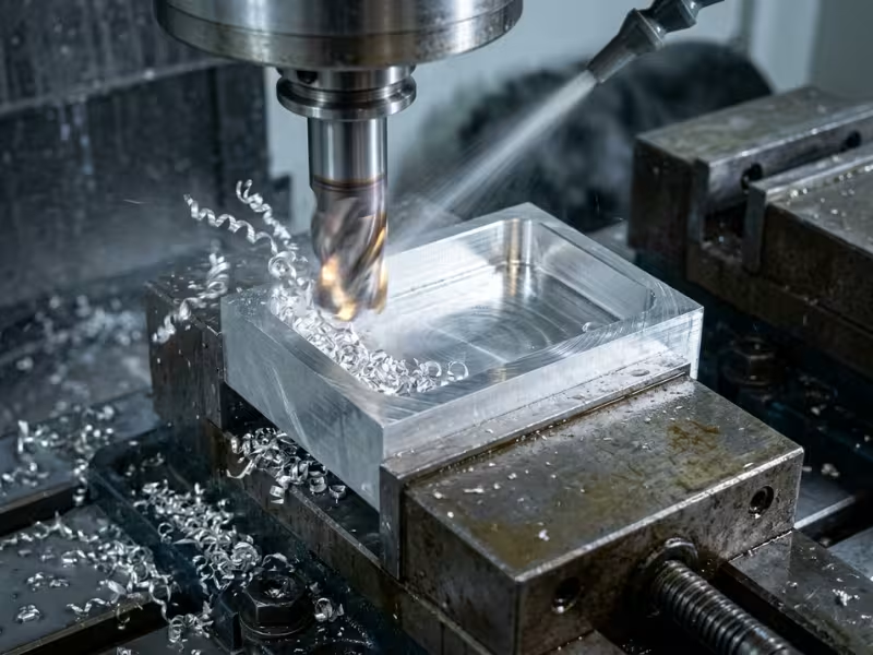
Chips tell you the most. In steel, healthy chips come off as tight C-shapes or 6-shapes with a straw to light-blue tint. Dark blue or purple chips mean too much speed. Long, stringy ribbons usually mean the feed is too light for the chipbreaker. In aluminum, look for small, shiny curls.
Sound comes next. A steady hiss means a stable cut. A high squeal points to chatter or rubbing. A deep growl, along with a climbing load meter, means the cut is too heavy.
The surface confirms what you heard. Even feed marks are normal. Wavy patterns mean vibration. A shiny, smeared look means the edge is rubbing instead of cutting.
Once the first part looks clean, you can start pushing.
Push Feed Before Speed
When I want more output, I raise feed first, in steps of about 10%. Feed adds metal removal almost one-for-one, and it barely changes edge temperature.
Speed works the other way. A 10% speed bump buys 10% more output but can cost a big share of tool life. I raise speed only after feed reaches the top of the chipbreaker’s range.
Stop when one signal slips. The load meter passes about 80%, the sound changes, or the chips darken. Then back off one step.
The right numbers also depend on the pass and the setup.
Match the Numbers to the Pass and the Setup
Roughing chases metal removal. Run feed near the upper middle of the range and keep speed moderate. Finishing chases size and surface. Drop the feed, raise the speed slightly, and take a light, even depth. With a 0.031″ nose radius, I often finish at 0.004–0.006 IPR.
Rigidity sets your ceiling. A boring bar past 4× its diameter, a long end mill, or a thin part in soft jaws will flex. In these setups, I reduce feed and depth first, not speed, because less force means less bending. If chatter continues, a 5–10% speed change often moves the cut out of resonance.
Workholding matters as much as the tool. If the part shifts or rings, no feed change will fix it. Grip closer to the cut, add support, or shorten the overhang.
Stainless and other work-hardening alloys need a firm, steady bite. Keep feed at or above the catalog minimum so the edge cuts under the hardened skin. Never let the tool dwell or rub at the end of a pass. If the cut runs hot, lower the speed and keep the chip load.
Common Mistakes With Speeds and Feeds
Most bad speeds and feeds I see don’t come from bad math. They come from a few habits that slip past the setup sheet. These five break the most tools.
Reading SFM as RPM. A chart lists 300 SFM for a 1/2″ carbide end mill in steel. Someone types S300 into the program. The tool barely turns, rubs, and wears out fast. The correct speed is about 2,292 RPM.
The reverse mistake burns tools. If you treat an RPM value as surface speed on a large diameter, you overspeed the edge. Check the unit on every chart before you enter a number.
Changing RPM without touching the feed. On a mill in G94, the feed stays fixed when you change spindle speed. Say you raise RPM 25% to clear built-up edge. Each tooth now takes a chip 20% thinner. If you drop RPM instead, the chip gets thicker. Recalculate the feed every time you edit the S value.
Feeding too light in stainless. In stainless steel CNC machining, operators often slow the feed in 304 or 316 to “go easy” on a new tool. The edge rubs instead of cutting, and that hardens the surface. Each pass then hits a tougher layer.
Keep the chip load at or above about 0.0015″ per tooth in milling. Don’t let the tool dwell at the end of a cut.
Ignoring chip thinning. At low radial engagement, the real chip comes out thinner than the programmed fz. At 10% stepover, it’s only about 60% of the feed per tooth. The edge rubs, heats up, and wears early.
To get a true 0.002″ chip at 10% engagement, program about 0.0033″ per tooth. Most CAM systems and toolmaker calculators handle this, but only if you enter the true stepover.
Copying numbers from another machine. A program that runs smoothly on a 40-taper machining center may chatter on a lighter 30-taper machine. Spindle power, holder runout, and tool stick-out all change the cut. Start borrowed numbers at about 80%. Then let the chips, sound, and load meter confirm them.
All five mistakes have the same fix: prove the number on your own setup before you trust it.
Feed Rate and Cutting Speed FAQ
What is the difference between feed rate and cutting speed?
Cutting speed is how fast the cutting edge moves across the workpiece surface, in SFM or m/min. Feed rate is how far the tool advances into the material, per revolution, per tooth, or per minute. Speed mainly controls heat and tool life. Feed mainly controls chip load, force, and finish.
How do you calculate cutting speed from RPM?
Multiply the diameter by π and the RPM. In imperial, SFM = (π × D × RPM) ÷ 12, with D in inches. In metric, Vc = (π × D × RPM) ÷ 1000, with D in mm. A 2″ bar at 760 RPM runs at about 398 SFM.
How do you convert cutting speed to spindle speed?
Reverse the formula: RPM = (SFM × 12) ÷ (π × D), or RPM = (Vc × 1000) ÷ (π × D). A 12 mm end mill at 150 m/min needs about 3,979 RPM. I round down slightly to protect the edge. Then I calculate feed from the rounded number.
What happens if feed rate is too low?
The edge rubs instead of cutting. That builds heat, glazes the surface, and wears the tool early. In 304 and 316 stainless, rubbing also work-hardens the surface, so each pass hits a tougher layer. Chips often come off long and stringy because the chipbreaker can’t work.
What happens if cutting speed is too high?
Heat builds at the edge faster than the tool can shed it. You’ll see fast flank wear, cratering, burned end mill corners, and dark blue or purple chips in steel. With carbide in steel, a 20% speed increase can cut tool life roughly in half. Drop the speed 10–15% and check again.
How do speeds and feeds differ between turning and milling?
Turning uses the workpiece diameter to find RPM and sets feed per revolution (fn). Milling uses the tool diameter and sets feed per tooth (fz). You then multiply fz by the flute count and RPM to get table feed. Lathes in G95 adjust feed with RPM automatically. Mills in G94 don’t, so recalculate feed every time you change spindle speed.
Run the Numbers on Your Next Job
Speed and feed do different jobs. Speed sets heat and tool life. Feed sets chip load and finish. When a cut goes wrong, that split tells you which number to change.
The math always runs in one order: pick Vc, calculate RPM, then calculate feed. If you change RPM, recalculate feed.
So pick one real job on your schedule. Look up Vc in the tool catalog, run both calculations, and record the results on your setup sheet. Then note what the first part shows you. Your own tested numbers will beat any chart.