An engineer sends me a drawing with twelve holes, two slots, and a pocket. Then comes the question I hear every week: does this part need milling, drilling, or both?
The answer shapes the quote, the setup, and the lead time.
Milling uses a rotating cutter that moves across the part to shape flats, slots, pockets, and contours. Drilling feeds a rotating drill straight down to make round holes.
That is the core difference. Drilling makes holes. Milling makes shapes.
Most real parts need both. I’ll show you how to sort each feature so you can plan and quote with confidence.
CNC Milling vs Drilling: The Core Difference
When I review a drawing, I don’t start by asking which machine to use. I start by asking what each feature needs the cutter to do. That one question separates milling from drilling.
Drilling moves in one direction. The drill spins and feeds straight into the material along a single axis, usually Z. The tip does the cutting, and the flutes carry chips back up and out. The drill itself sets the hole size. A 10 mm drill makes a hole close to 10 mm, whatever the part looks like around it.
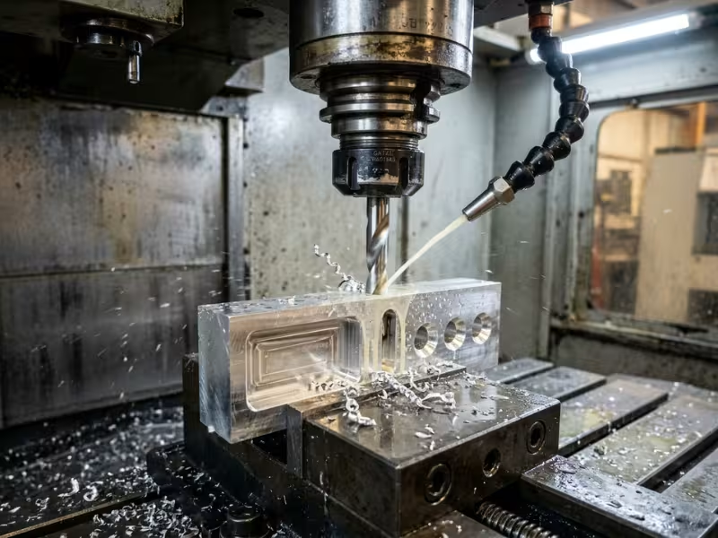
Milling moves in many directions. An end mill cuts mostly with its sides. The machine drives it across the part in X, Y, and Z. That lets one tool face a surface, cut a slot, clear a pocket, or trace a curved profile.
In practice, the split looks like this:
- Drilling is feature-specific. It does one job, round holes, and does it fast.
- Milling is geometry-flexible. It shapes almost anything the tool can reach, including non-round openings.
Many buyers miss one point. Most machining centers do both. In a typical CNC machining service workflow, the spindle that mills a pocket can swap in a drill and finish a bolt pattern a minute later.
So the real decision rarely depends on which machine you own. It depends on the type of each feature, how many setups the part needs, and what each feature costs to make. As a working rule, standard round holes go to the drill. Flats, slots, pockets, and profiles go to the mill.
Quick Comparison Table
When a customer wants a fast answer, I sketch this table on the back of their drawing. It shows where each process wins and where it falls short.
|
Factor |
CNC Milling |
CNC Drilling |
|---|---|---|
|
Primary purpose |
Shapes surfaces and non-round features |
Makes round holes |
|
Tool motion |
Cuts sideways while moving in X, Y, and Z |
Feeds straight down along one axis |
|
Typical features |
Flats, slots, pockets, contours, profiles |
Through holes, blind holes, bolt patterns |
|
Speed for hole-making |
Slower, since it circles each hole in passes |
Fast, with one plunge per hole |
|
Flexibility for complex geometry |
High, since one tool can cut many shapes |
Low, since the drill sets the hole size |
|
Usual setup/programming effort |
Moderate to high |
Low, using simple hole cycles |
|
Typical follow-up operations |
Finishing passes, deburring |
Reaming, tapping, countersinking, deburring |
|
Best fit use cases |
Housings, brackets, molds, prototypes |
Mounting plates, flanges, hole-heavy panels |
Use this table to sort individual features, not whole parts. Most drawings land in both columns.
How Milling and Drilling Work in Real Jobs
Definitions only get you so far. On the shop floor, each process has clear limits, and many costly quotes come from pushing a tool past them. Here’s where each one shines and where it starts to struggle.
Where Milling Earns Its Keep
Milling handles almost every feature that isn’t a plain round hole. I rely on it for:
- Faces. A face mill skims a saw-cut surface flat in a few passes. That face often becomes the datum for every hole that follows.
- Pockets. An end mill clears material inside a boundary, such as a circuit board cavity or a weight-saving recess.
- Slots. Keyways, T-slots, and adjustment slots let parts slide into position.
- Contours. Outer profiles, curved walls, chamfers, and 3D surfaces all come from milling.
- Non-round openings. Square cutouts, D-shaped holes, and oval windows need a tool that moves sideways.
This is why a dedicated CNC milling service becomes essential once a part needs flats, slots, pockets, or tightly controlled profiles.
Plan for two limits. First, an end mill always leaves a radius in inside corners equal to its own radius. Truly sharp corners need EDM or a design change. Second, deep pockets need long tools, and long tools flex. A practical limit is often a pocket depth of about four times the tool diameter.
Where Drilling Wins
When a drawing calls for round holes, drilling is usually the fastest route. It covers:
- Through holes for bolts, pins, and cable pass-throughs.
- Blind holes, often for tapped threads. These leave a cone-shaped bottom from the drill point, usually 118° or 135°. If you need a flat bottom, call it out.
- Repeated patterns. A canned cycle can drill a 40-hole bolt grid with a few lines of code.
- Standard diameters. Metric, fractional, letter, and number drills sit on most shop shelves.
- Deep holes. In many jobs, standard drills handle about three to four times their diameter in one pass. Beyond that, peck drilling retracts the drill to clear chips. Through-coolant drills can often reach 10× diameter at production speed.
Drills have one weak point. They tend to wander when they first touch the surface. A quick spot drill gives the tip a starting point and keeps the hole on position.
Why One Tool Shouldn’t Replace the Other
I see this mistake in both directions, and it costs money either way.
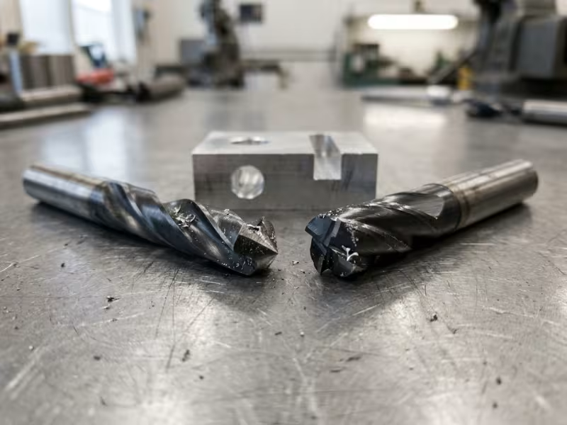
A drill can’t mill. Its cutting edges sit at the tip. The sides only guide it inside the hole. Push it sideways, and it rubs, deflects, and often snaps. Carbide drills break especially fast under side loads.
An end mill can make holes, but rarely as well. Circle or helical milling helps with odd sizes, large diameters, or flat-bottom holes. For standard holes, it usually falls short on cycle time, roundness, and straightness. Long, thin end mills bend in deep holes and leave tapered walls.
My rule is simple. Drill standard holes, then ream or bore the ones that need tight fits. Save the end mill for holes no drill can make.
When to Choose Milling, When to Choose Drilling
Most quoting problems I catch don’t come from bad machining. They come from planning the wrong process for a feature. So go through your drawing one feature at a time and ask three questions: Is it round? Is it a standard size? Does its position matter to anything else?
Your answers point to milling, drilling, or both.
Choose Milling When the Feature Has a Shape
If a feature needs more than a diameter and a depth to describe it, treat it as a milling feature. Choose milling when your part needs:
- Flats such as sealing faces, mounting pads, and reference surfaces.
- Slots and pockets like keyways, adjustment slots, and cavities.
- Contours including outer profiles, curved edges, and chamfers.
- Tight control on non-hole features. If a slot must hold a sliding fit, a finishing pass lets the programmer adjust size directly.
- Changing geometry. Prototypes change often. Moving a pocket in CAM takes minutes and needs no new tooling.
Choose Drilling When the Job Is Mostly Holes
Drilling wins when round holes fill most of the drawing. Think of a mounting plate with 30 clearance holes, or a flange with a bolt circle. Look for these signs:
- Holes make up most of the features. A canned cycle handles them with very little programming.
- The diameters match standard drills. A 5.0 mm tap drill for M6 or a 6.6 mm clearance hole is easy to source. An odd size like 6.37 mm forces a special drill or a slower milled hole.
- Cost per hole matters. Across 500 parts with 20 holes each, the gap between drilling and circle milling can add up to hours of spindle time.
One habit saves my customers real money. Check a drill chart before you set a hole diameter. Rounding to the nearest standard size rarely changes function, and it often lowers the price.
When the Right Answer Is Both
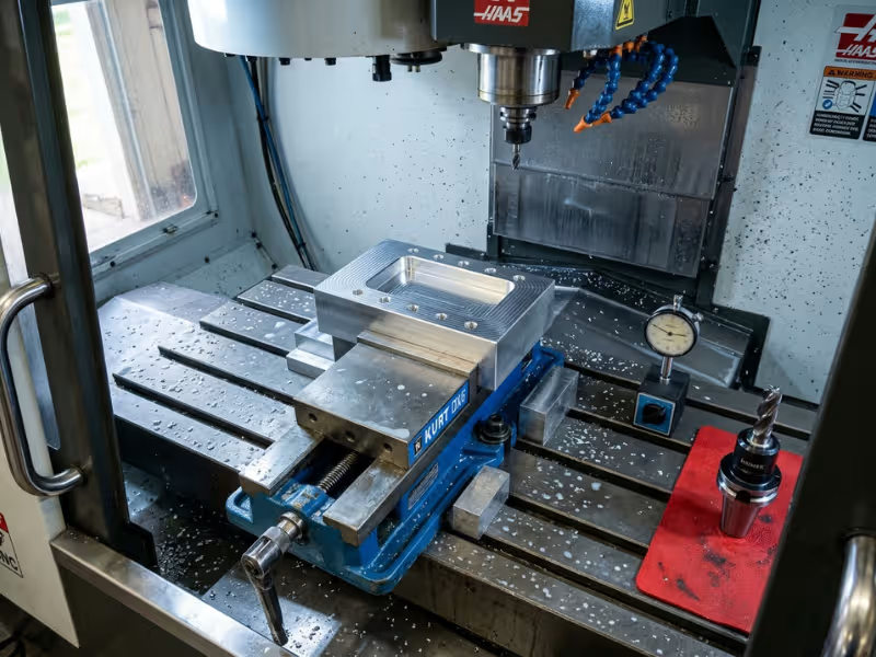
Most parts I quote land here. The smart move isn’t picking one process. It’s putting them in the right order, ideally in a single setup:
- Face the top surface so you have a flat, true reference.
- Mill the datum features, such as edges, bosses, or a locating pocket.
- Spot drill every hole location.
- Drill, then tap, ream, or countersink as required.
- Finish the remaining milled features, such as outer profiles.
Each time an operator reclamps a part, its position shifts a little. Even careful refixturing can add around 0.02–0.05 mm of error. When the datums and holes come from the same clamping, they share one coordinate system. Hole-to-edge positions stay consistent from the first part to the last.
Accuracy, Surface Finish, and Cost: What Actually Changes
Process choice shows up in three places: how close features measure, how they look and feel, and what the invoice says. I walk customers through all three before we agree on a quote.
How Accurate Each Process Really Is
A standard twist drill is fast, but it isn’t a precision tool. On a typical machining center, I generally expect a drilled hole within about ±0.05–0.1 mm on diameter. Holes often run slightly oversize.
Position is the bigger risk. A drill tip can wander as it enters the material, especially on curved or angled surfaces. A spot drill fixes most of that.
So when a hole holds a dowel pin, a bearing, or a press-fit bushing, I don’t trust the drill alone. I drill slightly undersize, then:
- Ream it for a round, straight hole. Reaming commonly reaches H7, which allows about +0.015 mm on a 10 mm hole.
- Bore it when position matters as much as size, or when no standard reamer fits the diameter.
Milling gives the programmer direct control over edges, slots, and profiles. With the right setup and a sharp tool, a finishing pass can hold around ±0.02 mm on a slot width. But tighter milled tolerances need lighter passes and more inspection. Precision is available, but it isn’t free.
Surface Finish and Secondary Operations
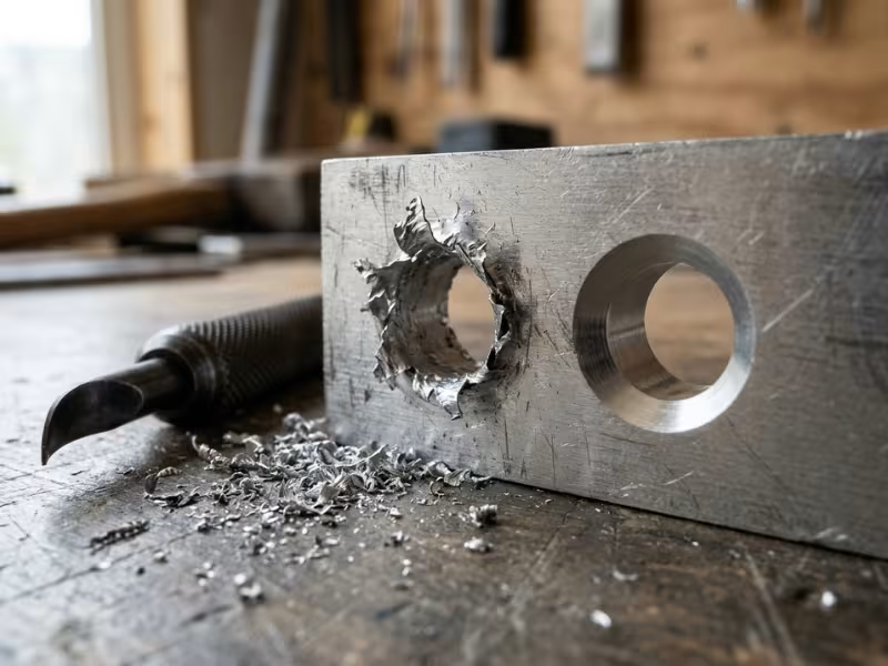
Drilling rarely produces the final surface. A drilled hole often comes out around Ra 3.2–6.3 µm, and the drill leaves a burr where it breaks through. On thin aluminum plates, that burr can stop a mating part from sitting flat.
Most drilled holes need at least one follow-up step:
- Deburring at the exit, by hand or with a back-chamfer tool
- Reaming for smoother walls, often Ra 0.8–1.6 µm
- Tapping for threads
- Countersinking or counterboring so screw heads sit flush
Milled walls carry their own marks. Roughing passes leave visible steps. If a wall seals against a gasket or slides against another part, I add a light finishing pass, which often brings it to Ra 1.6 µm or better.
If burr control or wall finish matters, define your CNC machining surface finish expectations before the process plan is locked.
Where the Money Goes
Per feature, drilling usually wins on speed. If your part is mostly holes, drilling keeps cycle time low. Milling wins when the geometry isn’t round, because one end mill can cut a pocket, a slot, and a profile without a tool change.
Still, cycle time is only part of the bill. On many jobs I quote, setup and handling cost more than spindle time.
Here’s a typical case. Saving 20 seconds per part across 50 parts saves under 17 minutes. Removing one extra setup can save an hour or more. Fewer setups, standard hole sizes, and tolerances only where they matter usually cut a quote more than any faster tool.
Common Design and Process Mistakes
Most expensive problems I see start on the drawing, not the machine. These five mistakes add the most cost, scrap, and back-and-forth.
Treating Drilling as “Simple Milling”
Drilling looks easy, so people plan it last. But a drill cuts at the tip, traps chips inside the hole, and wanders when the surface isn’t flat. Skip the spot drill on a cast or angled face, and holes drift off position. Place a hole on a curved wall with no flat start, and the drill can deflect or break.
Tight Tolerances on Every Hole, With No Hole Type
I often get drawings where every hole carries ±0.01 mm. Most turn out to be bolt clearance holes that work fine at ±0.1 mm. That blanket tolerance forces reaming or boring on holes that never needed it.
Mark each hole as clearance, tap, ream, or press-fit. Add full thread callouts, such as M6×1.0, and give fit classes like H7 only where pins or bearings go.
Custom Hole Sizes Everywhere
A designer enters 6.37 mm because the CAD model rounded that way. The shop then needs a special drill or a slower milled hole. Use standard sizes, and limit how many you use. A part with three hole sizes runs faster than one with eleven.
Ignoring Chips in Deep Holes
Holes deeper than about four times their diameter tend to trap chips. Packed chips raise heat, scratch walls, and snap drills. Peck cycles and through-coolant drills solve most of this. On the design side, drill from both sides when possible, and specify the shallowest depth that works.
Splitting Operations Across Setups
Some shops mill on one machine, then move the part to a drill press. Each move breaks the link between datums and holes. If holes must line up with milled features, ask for both in the same setup. When a second setup is unavoidable, define clear datums so both operations measure from the same reference.
Real Part Scenarios: Which Process Makes More Sense?
Rules make more sense on real parts. Here are three jobs I quote often and how I plan each one.
Mounting Plate with Many Bolt Holes
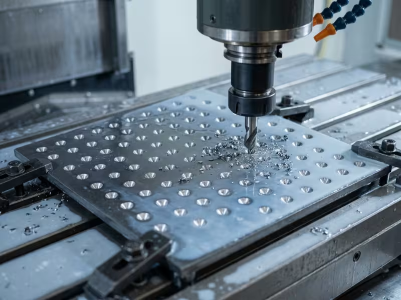
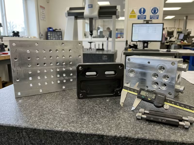
Picture a 10 mm aluminum plate, 300 × 200 mm, with 36 M8 clearance holes and four M6 tapped holes. Drilling does almost all the work.
I spot drill every location. A 9 mm drill runs the clearance holes in one canned cycle. A 5 mm drill and an M6 tap handle the threads, and a back-chamfer tool cleans the exit burrs. Milling only faces the stock if needed and cuts the outer profile.
Bracket with Slots, Pockets, and Threaded Holes
Now take a steel bracket with two adjustment slots, a weight-saving pocket, and four M5 tapped holes. Neither process can do this alone.
The slots need an end mill because a bolt must slide along them. I finish them to width so the bolt moves freely without play. The same end mill clears the pocket. The tapped holes get a spot drill, a 4.2 mm tap drill, and a tap. If the bracket needs a second side, I mill a reference edge first so the holes stay aligned with the slots.
Housing or Manifold with Critical Flatness and Hole Location
A hydraulic manifold raises the stakes. Say the drawing calls for a sealing face flat within 0.02 mm and two dowel holes within ±0.01 mm of the datum edges.
Milling sets the foundation. I face the sealing surface, then mill the datum edges square to it. Next, I drill the dowel holes undersize and ream them to H7. If position matters more than a reamer can control, I bore them, because a reamer follows the existing hole while a boring bar corrects it. Cross-drilled passages get peck drilling and a deburr where they meet.
All three jobs follow the same pattern. Count the holes, then look at what else the part needs. That feature mix decides the process plan.
What to Check Before You Send a Part for Quote
The fastest, most accurate quotes I send go to customers who answer my questions before I ask them.
Sort every feature first. Mark every round hole in one color and every flat, slot, pocket, and profile in another. You’ll see how the work splits and spot odd hole sizes worth changing.
Give each hole a job. Label each one:
- Clearance: A general tolerance like ±0.1 mm usually works.
- Tapped: Add the full callout and depth, such as M6×1.0, 12 deep.
- Reamed or press-fit: Add a fit class like H7, only where needed.
- Countersunk or counterbored: Include the angle or depth.
Flag what touches other parts. Circle surfaces, pockets, or slots that seal, locate, or mate. Keep everything else at general tolerance so you don’t pay for precision you’ll never use.
Ask about setups. Put this in your RFQ: “Can you finish this part in one setup?” If parts mix milled features, drilled holes, and tight fits, an experienced contract machining partner can cut unnecessary setups and quoting delays.
Send the 3D model with the 2D drawing. The model shows the geometry. The drawing shows what matters.
CNC Milling vs Drilling FAQ
These are the questions customers ask me most often.
Can a CNC milling machine do drilling?
Yes. Most CNC mills and machining centers drill as well as they mill. Dedicated CNC drills mainly make sense for high-volume, hole-heavy work like large plates.
Which is cheaper, CNC milling or CNC drilling?
Drilling usually costs less per hole. But the total price depends on the feature mix, tolerances, and number of setups. Standard hole sizes and a single setup often lower a quote more than the process choice itself.
What is the main difference between a drill bit and an end mill?
A drill cuts at its tip and feeds straight down. An end mill cuts mainly with its sides and moves across the part. Never push a drill sideways, because it can deflect and snap.
How accurate are CNC-drilled holes?
On a typical machining center, expect roughly ±0.05–0.1 mm on diameter. For pins, bearings, or press fits, drill undersize and ream to a fit like H7, or bore when position is critical.
Is CNC drilling faster than CNC milling?
For standard round holes, usually yes. A drill finishes a hole in one plunge, while circle milling can take several times longer. Deep holes slow drilling because peck cycles stop to clear chips.
Can one setup handle both milling and drilling?
Yes, and on most parts it should. Facing, datum milling, drilling, and tapping in one clamping keeps holes and milled features in one coordinate system. That avoids the small shifts reclamping can add.
Holes, Shapes, and Your Next Step
The core rule stays simple. Drilling creates round holes fast. Milling carves the flats, slots, pockets, and profiles around them.
Yet most parts I quote don’t force a choice. They need both, in the right order and ideally in one setup. That keeps holes aligned and costs down.
So start with your drawing. Mark every hole in one color and every milled feature in another. Label each hole’s job and flag the surfaces that mate with other parts.
Then send the model and drawing together, so your machining partner can quote accurately from the start. You’ll get a cleaner quote and parts that fit the first time.