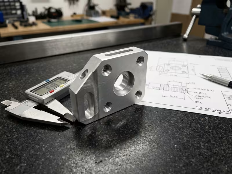
True position is one of the most miscalculated controls in GD&T, not because the math is hard, but because the drawing is easy to misread.
I have watched skilled engineers get the arithmetic right and still land on the wrong answer. The problem almost never lives in the square root.
It hides in the details. People pull coordinates from the wrong dimensions. They swap the datum sequence. They forget to multiply by 2. They add MMC bonus tolerance when the callout never allowed it.
Each mistake looks small. Each one flips a good part into a reject, or lets a bad part ship.
This guide focuses on the parts that actually decide your result: how to read the callout, how to run the calculation, and how to avoid the inspection errors that trip up so many people.
What True Position Actually Controls
Before any formula, get one idea straight. True position controls where a feature is allowed to be, not how big that feature is.
That single distinction clears up more confusion than any definition ever will.
It Controls Location
Position pins down the location of a feature — usually the axis of a hole or shaft, or the center plane of a slot. It asks a simple question: did that feature land where the drawing said it should?
It Does Not Control Size or Form
Position says nothing about how big the hole is, how smooth the surface finished, or whether the feature holds its shape on its own. Those are separate checks with separate tolerances. A hole can meet its size tolerance and still fail position if its axis falls outside the allowed zone.
The Zone Is Diametrical
Here’s the part people miss. The tolerance zone is diametrical — a circle in 2D thinking, a cylinder in 3D. That’s why the calculated result gets compared to a diameter value, not a simple X or Y offset.
Read the Drawing First: What You Need Before You Calculate
Before you calculate anything, read the feature control frame as a set of instructions, not just a number.
That frame tells you what is being controlled, how large the tolerance zone is, whether bonus tolerance is allowed, and which datum structure defines the measurement frame. Rush past it and every number that follows carries your mistake forward.

Break the Feature Control Frame Apart
Don’t start calculating the moment you spot a number. Confirm four things first:
- The geometric control is position.
- The tolerance is diametrical.
- The modifier is RFS, MMC, or LMC.
- The datum references, and their order.
Pull Coordinates from Basic Dimensions Only
The coordinates you use in the formula come from basic dimensions, not from general drawing dimensions. Those boxed numbers define the exact intended location and carry no plus/minus of their own.
Grab the wrong nominal values and the rest of the calculation can be mathematically perfect and still wrong.
Respect the Datum Order
Datum order is not formatting. It defines how the part is oriented and how location is measured. Primary, secondary, and tertiary datums build the reference frame in that exact sequence.
Swap the order and you’ve built a different coordinate system. The same measured point can pass in one frame and fail in another. If the datum reference frame is wrong, the result is meaningless even when the formula is right.
Read the Modifier for Its Effect
You don’t need a full lecture on material conditions here. You just need to know how each one touches the allowable tolerance:
The modifier changes the allowable tolerance, not the way the base formula runs. Most confusion starts when people mix up the measured true position value with the allowed tolerance after MMC bonus.
|
Drawing element |
What to identify |
Why it matters |
|---|---|---|
|
Position symbol |
Confirms positional control |
Keeps it separate from size or profile |
|
Diameter symbol |
Shows the diametrical zone |
Explains why the result compares to a diameter |
|
MMC/LMC/RFS |
Affects allowable tolerance |
Changes pass/fail logic |
|
Datum sequence |
Establishes the reference frame |
Wrong order gives wrong result |
|
Basic dimensions |
Gives nominal coordinates |
Inputs for the calculation |
This kind of print discipline is exactly what separates a clean CNC machining service from one that ships surprises.
The True Position Formula, Explained Simply
Here’s the formula for a 2D check:
The formula itself is simple. The important part is understanding what kind of value it produces.
What dX and dY Are
They’re the deviations: measured minus basic, for each axis. They can come out positive or negative. Direction matters while you subtract, but it drops out once you square the values.
Why You Square and Add
Position error isn’t a one-axis problem. A feature can drift in both X and Y at the same time. Squaring each deviation and adding them captures that combined offset in space, then the square root pulls it back to a single distance.
Why You Multiply by 2
This is the step people forget, so pay attention here.
The square root term gives the radial deviation from true location — a radius. Position tolerance is diametrical. Multiplying by two converts that radial offset into the diametrical value your tolerance actually uses.
The same logic extends to 3D by adding dZ under the root. But only reach for 3D when the drawing and measurement setup genuinely call for it.
How to Calculate True Position Step by Step
A true position check becomes much easier when you separate the measured result from the allowable tolerance.
First calculate what the feature actually did. Then decide how much deviation the drawing allows. Those two numbers are related, but they are not the same thing.
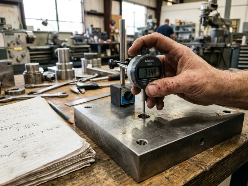
Here’s the flow, one action per step:
|
Step |
Action |
Example value |
|
|---|---|---|---|
|
1 |
Basic X, Y |
2.000, 1.500 |
|
|
2 |
Measured X, Y |
2.008, 1.494 |
|
|
3 |
dX, dY |
0.008, −0.006 |
|
|
4 |
Square deviations |
0.000064, 0.000036 |
|
|
5 |
Sum and square root |
0.010 |
|
|
6 |
Multiply by 2 |
0.020 |
|
|
7 |
Compare to tolerance |
0.020 vs 0.030 |
|
|
8 |
Result |
Pass |
Worked Example: Pass or Fail Under RFS
Let me walk you through the cleanest version of the check. One hole, two dimensions, no modifiers. Every harder case builds on this.
Under RFS, the decision is straightforward: calculate the true position value and compare it directly to the stated tolerance.
The Setup
Picture a single hole on a bracket. Basic location: X 2.000, Y 1.500. The feature control frame calls for a position tolerance of 0.030, diametrical, with no modifier attached.
That missing modifier matters. No modifier defaults to RFS, so no bonus tolerance will shift the limit. The pass/fail decision rides entirely on the measured positional error.
The Math
The part comes off the machine measuring X 2.008, Y 1.494.
- dX = 2.008 − 2.000 = 0.008
- dY = 1.494 − 1.500 = −0.006
Square and add:
- 0.008² = 0.000064
- 0.006² = 0.000036
- Sum = 0.000100
Square root: √0.000100 = 0.010. That’s the radial offset. Multiply by 2 for the diametrical value:
The Call
The result is 0.020. The tolerance is 0.030. It sits inside the limit, so the hole passes.
Worked Example: How Bonus Tolerance Works at MMC
Same Hole, One New Detail
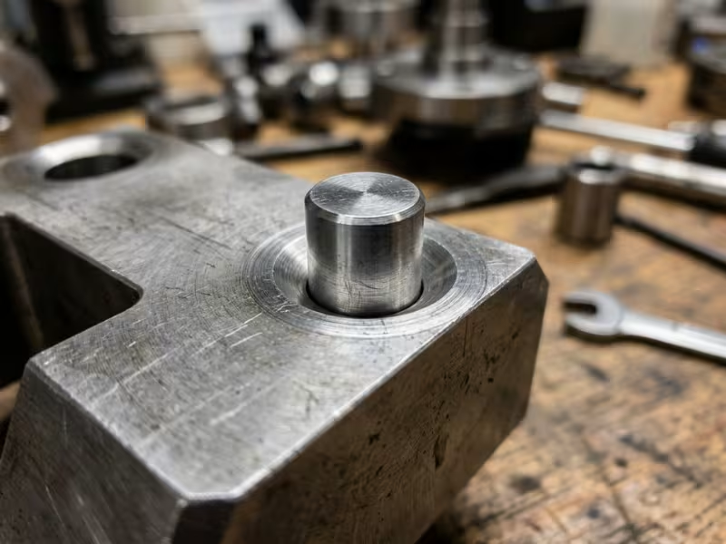
Reuse that bracket hole, but add a size tolerance. The drawing now calls out a position tolerance of 0.030 at MMC, with an MMC hole size of 10.000 — the smallest allowed diameter.
When the hole runs bigger than MMC, it clears its mating pin more easily. That extra clearance buys extra positional freedom. We call it bonus tolerance.
Working the Numbers
Inspection reports the hole at 10.012.
- Actual size − MMC size = bonus
- 10.012 − 10.000 = 0.012
Add that bonus to the stated tolerance — to the allowable limit, not the measured result:
Say the measured true position comes out to 0.038, calculated the same way as always. Compare it to the new limit:
|
Item |
Value |
|---|---|
|
Stated position tolerance at MMC |
0.030 |
|
MMC hole size |
10.000 |
|
Actual hole size |
10.012 |
|
Bonus tolerance |
0.012 |
|
Total allowable position |
0.042 |
|
Measured TP result |
0.038 |
|
Outcome |
Pass |
A 0.038 result would have failed under a plain 0.030 tolerance. The larger hole created enough bonus to accept it. Same error, different outcome, driven entirely by size.
The Mistake I See Most
People add bonus to the wrong number. They calculate 0.038, then adjust that measured value by the bonus and report a made-up figure. That’s backwards.
A Quick Word on LMC
LMC flips the logic — bonus grows as the feature moves toward its largest material state, often to protect a minimum wall thickness. It behaves differently enough that you should never apply MMC bonus rules to an LMC callout.
Pattern of Holes: What Changes and What Does Not
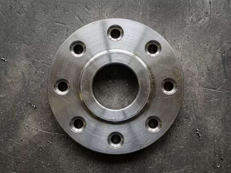
Move from one hole to a bolt circle and part of you wants to treat it as a new problem. It isn’t. But it isn’t a straight copy-paste either.
What Stays the Same
Every hole still has a center, a basic location, and a measured location. You run the same square-root-then-double routine per feature. Your calculation habits don’t go out the window.
What Changes
A pattern callout often controls the holes as a group. A hole pattern still involves individual feature locations, but the drawing may control the group in ways a single-hole calculation never captures. Spacing between holes and the rotation of the whole set can matter as much as any one center. A pattern can twist as a unit while each hole looks fine alone.
Composite Callouts Are Different
A composite callout looks like a stacked, two-line version of a normal one. It is not read the same way. The upper segment usually controls the pattern’s location to the datums; the lower segment controls the tighter feature-to-feature relationship. If the callout is composite, don’t assume simple single-segment logic applies. For dense patterns, inspection software or a formal standards review earns its keep.
How to Check True Position Without a CMM
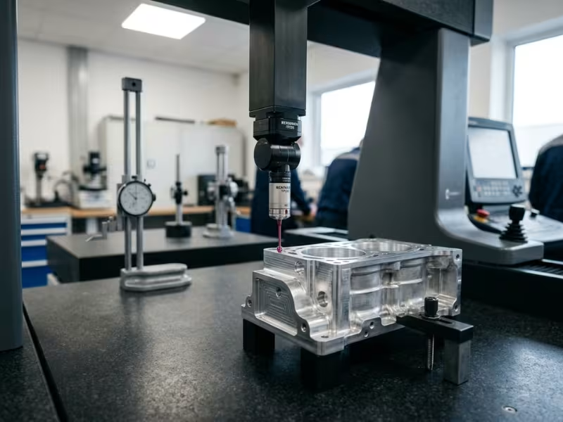
Good news up front: you do not need a CMM to calculate true position, but you do need trustworthy coordinates.
The formula never asked for a coordinate measuring machine. It asked for where the feature should be and where it landed.
Where Coordinates Come From
The Catch
That’s also why a hand calculation and a CMM result won’t always match — different feature extraction, different datum simulation, different rounding.
A functional gauge answers a different question entirely: not what the true position value is, but whether the part clears a functional boundary. Clean pass/fail, no number.
|
Method |
Best for |
Main limitation |
|---|---|---|
|
CMM |
Complex geometry, tight tolerances |
Cost and programming time |
|
Vision system |
Flat parts, fast coordinate checks |
Setup and lighting sensitivity |
|
Height gauge / manual |
Simple layouts, looser tolerances |
Higher operator and alignment error |
|
Functional gauge |
Production pass/fail checks |
Gives no numeric TP result |
For simple flat features with generous tolerances, the bench holds up fine. Push toward tight tolerances or angled axes and confidence drains fast — that’s when the CMM earns its place. Reliable location data is the backbone of solid inspection and shipping, whatever tool produces it.
Common Mistakes That Cause Bad Results
Notice what these share. Not one is a math failure. Slow down at the front end, and most disappear before you touch the calculator. That same discipline underpins reliable CNC metal machining across every material.
Quick Checks Before You Sign Off a Result
A short sanity check takes less time than sorting out a false reject later. Run these seven before your name goes on the report:
In practice, these last checks catch more errors than redoing the square root.
True Position vs Other Controls: Keep It Short
Not every location-related problem is a true position problem.
Position is usually the right control for holes, pins, and repeatable feature locations. It fences off a diametrical zone and asks whether the axis or center plane landed inside it. Profile and concentricity answer different questions.
|
Control |
Main purpose |
Typical use |
|---|---|---|
|
Position |
Controls feature location |
Holes, shafts, bolt patterns |
|
Profile |
Controls form and location together |
Complex surfaces and contours |
|
Concentricity |
Controls derived median points |
Limited, specialized cases |
|
Symmetry |
Controls median-plane relationship |
Specific center-plane cases |
Frequently Asked Questions
Where the Real Skill Lives
After all the math, here’s the truth I keep coming back to: true position was never the hard part. The formula behaves. It gives an honest number every time you feed it honest inputs.
That’s why reading the drawing has to come first. The formula only rewards you when the nominal location, the datum structure, and the modifier were all read correctly before you started. Correct interpretation is what keeps a clean calculation from becoming a bad decision.
Hold on to the one idea that clears up modifiers: MMC changes the allowable tolerance, nothing else. Calculate the same way you always do, then let actual feature size adjust how much room the drawing gives you.
So if I leave you with anything, let it be this. You don’t win at true position by memorizing more definitions. You win with discipline — confirming your inputs, respecting the datum frame, applying bonus only when the callout allows it, and checking against the right limit. Do that consistently, and the mistakes that plague so many inspections quietly stop happening. The math was always going to cooperate. The rest is on you.