A part clings to the core during ejection, drags across the steel, and comes out scuffed — all because someone shaved a half-degree of draft to protect a wall thickness spec. That single decision, made in CAD weeks earlier, is what core and cavity injection molding lives or dies on. The mold ran fine; the geometry didn’t.
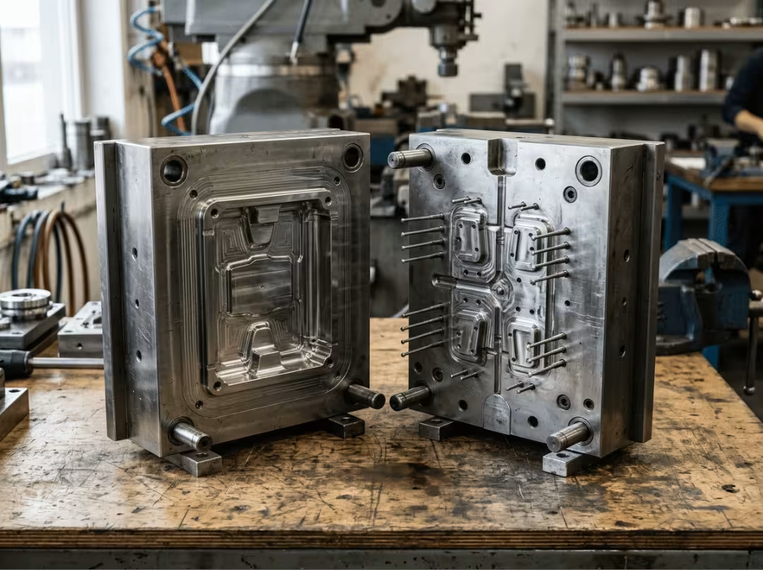
The definitions are quick. The cavity is the half that forms the outside of your part. The core is the half that forms the inside. Together they shape every dimension, radius, and surface your finished part will ever have.
Here’s why that matters more than it sounds. The choices you lock in on paper — draft, wall thickness, cooling, ejection — set your part quality, cycle time, tooling cost, and mold life before a single shot runs. Get them right, and the tool practically runs itself. Get them wrong, and you’re looking at scrapped parts and a mold you re-cut at real expense. This guide gives you a repeatable way to design the core and cavity right the first time, and to trace problems back to their root when they show up.
What the Core and Cavity Actually Do
The two halves aren’t mirror images, so they don’t split the work evenly. They do different jobs, and that asymmetry drives most of the decisions that follow. The cavity owns how the part looks. The core owns its geometry, its cooling load, and its ejection.
The molding cycle ties them together in seconds: the mold closes, plastic injects and packs, the part cools, the mold opens, and ejector pins push the part off the core. Simple to say, but where the part ends up — and how clean it comes out — depends entirely on how you designed these two halves to meet.
The Cavity: The Outside Surface
The cavity creates your part’s exterior surface, its parting lines, and most of its cosmetic texture. It sits on the A-side of the mold, mounted to the stationary platen. When you care about a glossy face, a crisp logo, or a specific grain pattern, you’re really talking about the cavity. It defines what the customer sees and touches.
The Core: The Inside Geometry
The core forms the internal features — the walls, holes, recesses, and ribs. It mounts on the B-side, the moving platen, and carries the entire ejector system. Here’s the part people miss: the core runs hotter than the cavity because the thickest plastic wraps around it as the part shrinks onto the steel. That’s exactly why cooling and ejection design concentrate on the core side.
Picture a deep-draw housing, like a tall electronics enclosure. The plastic grips the core as it cools, the core soaks up the heat, and the ejector system has to break that grip cleanly. If the core runs too hot or the draft is too tight, the part sticks — and everything downstream suffers.
Where the two halves close, shut-off surfaces seal the melt and prevent flash. Vents at the parting line let trapped air escape ahead of the flow. And the alignment has to be dead-on, because any shift between core and cavity shows up as uneven wall thickness in the finished part.
Design Considerations That Make or Break the Mold
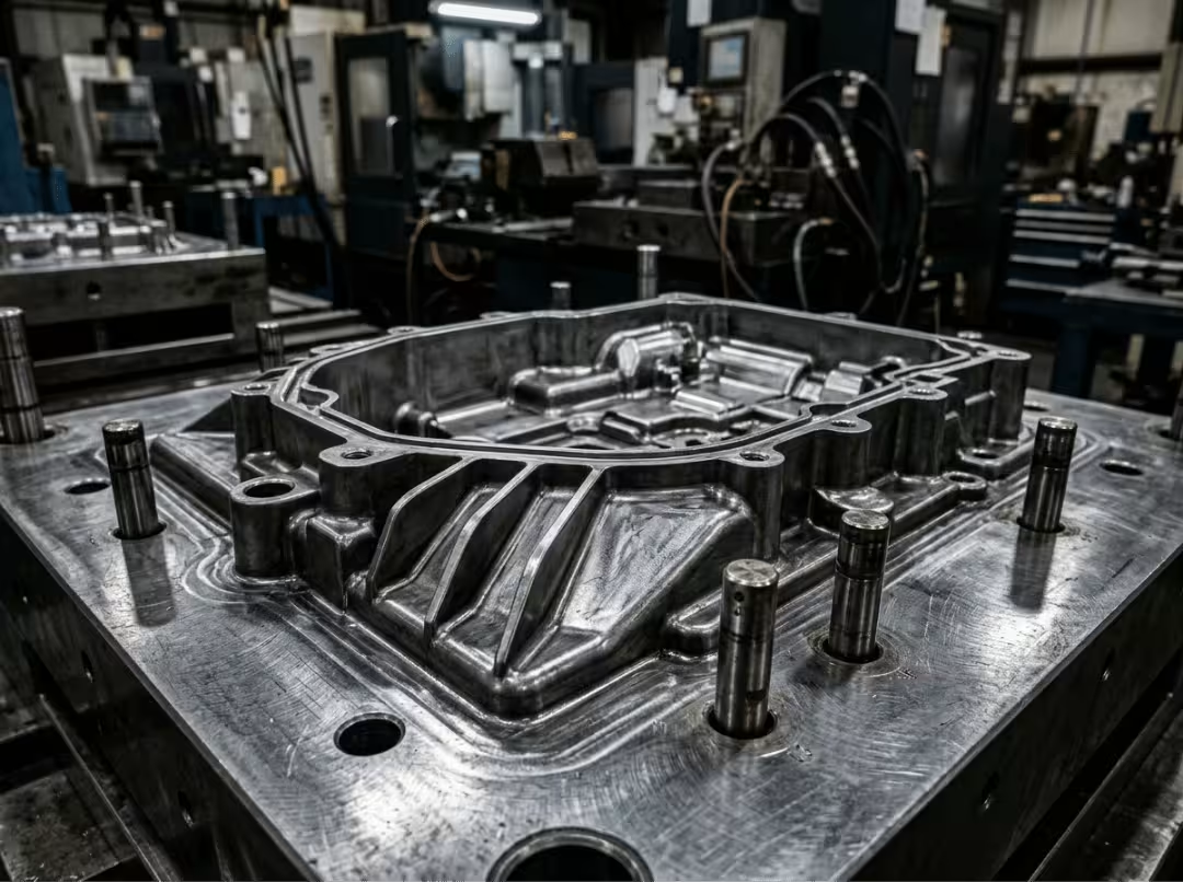
Most molding problems are designed in, not machined in. A shop can cut your steel perfectly and still hand you parts that sink, warp, or stick — because the trouble was baked into the geometry long before the tool existed. Nail draft, wall thickness, cooling, and ejection on paper, and the tool practically runs itself. Miss them, and no amount of parameter tuning at the press will save the part.
These four factors carry the weight. Give them the attention, and the rest tends to fall into line.
Draft Angles for Clean Ejection
Draft is the slight taper on any wall that runs in the direction the mold opens. Skip it, or cut it too thin, and the part fights the steel on the way out — you get drag marks, scuffing, stress whitening, or a part that sticks on the core and refuses to eject cleanly.
The working range is roughly 0.5 to 2 degrees per side. Shallow features can live at the low end; deep walls need more, because the part has more surface gripping the steel as it clears. Texture changes the math entirely. A textured surface needs about one extra degree of draft for every 0.001 inch of texture depth. Forget that, and the texture acts like teeth dragging across the part as it ejects.
Reach for more draft when the surface is textured, the core is deep, or a part clings during tryout. Adding draft in CAD costs nothing. Fixing it in hardened steel costs a re-cut.
Wall Thickness and Uniformity
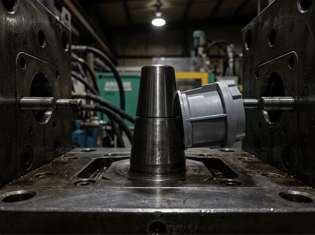
Uniform wall thickness is the single biggest defect preventer you have. Plastic wants to cool evenly, and when it can’t, it tells you — with sink marks, warpage, and dimensions that drift out of spec.
Thick sections are the usual culprit. A heavy boss or a chunky rib acts as a heat sink, holding heat long after the thin walls around it have frozen. As that thick zone finally cools and shrinks, it pulls the surface inward and leaves a visible sink on the show face. It’s a cosmetic killer on any Class-A surface.
The instinct is to crank up pack pressure to force more material in and fight the sink. Sometimes that helps a little. More often, coring out the thick section — hollowing it so the walls stay uniform — solves the problem outright and shortens cycle time as a bonus. Design the mass out instead of pressuring around it.
Cooling Channel Placement
Cooling affects cycle time, dimensional stability, and warp — three factors that determine whether a mold is profitable. Roughly two-thirds of the cycle is spent just pulling heat out of the part, so how you route the water matters as much as almost anything else in the tool.
The core deserves the most attention, because it runs hottest. Straight-drilled channels work on open geometry, but deep cores are tricky — you can’t drill a straight line into a tall, narrow core and expect even cooling. That’s where baffles and bubblers come in, forcing water up into the core to reach the heat where it concentrates.
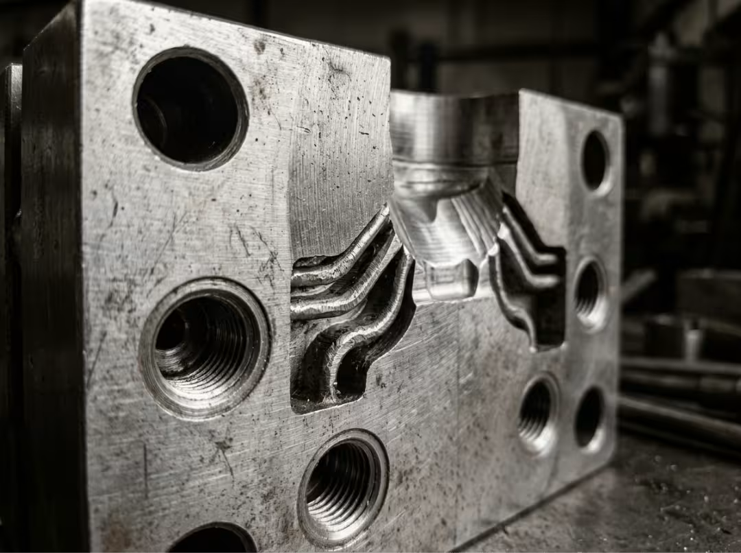
When a hot spot won’t clear with conventional channels, or cycle time is stuck no matter what you try, conformal cooling earns its cost. These are channels that follow the part contour, built with metal 3D printing, and they pull heat evenly from geometry that drilled lines simply can’t reach. Reach for them when the thermal problem is real, and nothing else moves the needle.
Ejection System Integration
Every part needs a way off the core, and the method you pick affects both reliability and appearance. Ejector pins are the default — cheap, simple, effective. Sleeves work around bosses and pins. Blades handle thin ribs. Lifters release internal undercuts as they eject.
The trade-off worth knowing: bigger pins resist bending and push harder, but they leave bigger witness marks. Smaller pins are gentler on cosmetics but bend under load. The fix is placement — put pins on non-cosmetic faces, ribs, and internal surfaces where a witness mark doesn’t matter. For parts that grip the core with real suction, like deep, smooth-walled housings, air poppets or a stripper plate break the vacuum and release the part without piling on more pins.
Beyond these four, a shorter set of levers still needs a decision. Undercuts — any feature that blocks straight ejection — force side actions like slides and lifters, or a collapsing core for internal threads. Each one adds cost and complexity, which is why a two-plate mold is simpler and cheaper than a three-plate mold whenever the geometry allows. Shrinkage runs 0.3 to 2.0 percent depending on the resin and its glass fill, and the tool has to be cut oversized to compensate — settle the tolerance class with your mold maker early, not after the first samples. And the parting line should hide on a non-cosmetic edge when the geometry lets it, because that’s where witness lines and flash live.
How Cores and Cavities Are Made
You don’t need to run the machines, but knowing which process fits which feature helps you understand your lead time, your cost, and what geometry is even possible to build.
CNC machining is the default. It cuts most contours and 3D shapes fast, accurately, and repeatably, whether the shop machines soft steel and heat-treats it afterward or hard-mills already-hardened blocks. Reach for CNC when the geometry is open enough for a cutter to physically access it — which covers the large majority of mold work.
EDM — electrical discharge machining, in both sinker and wire forms — erodes metal with electrical sparks instead of cutting it. That lets it produce sharp internal corners, deep narrow ribs, and detail in hardened steel a mill can’t touch. The catch is the electrode: someone has to make a graphite or copper electrode first, which adds lead time. Reach for EDM when you need a square internal corner or a deep slot that a rotating cutter physically can’t produce.
Metal 3D printing builds inserts with conformal cooling channels that follow the part contour. It shines on low-volume tools, prototypes, and thermally tricky zones where a drilled line can’t reach the heat. Surface finish, porosity, and size still limit it, so a hybrid approach — a machined base with a printed cooling insert — is common. Reach for printed inserts when a hot spot needs conformal cooling or the volume doesn’t justify a fully machined tool.
Surface finish is the last step and transfers directly to the part. The SPI scale runs from A (mirror-polished gloss) to D (dull, blasted), with chemical etching for textured patterns. Remember that texture adds draft requirements and tool cost, so decide the finish before the design is locked, not after.
Choosing the Right Steel
Match the tool steel to your production volume and your plastic — not to whatever the last job used. Volume and abrasiveness decide the grade; specialty metals solve specific cooling or corrosion problems.
- P20 — pre-hardened, cheaper, and fast to machine. Use it for low- to medium-volume tools where you don’t need extreme wear resistance.
- H13 — a hot-work steel that holds up to high volume and abrasive or glass-filled resins. Use it when the part count is high, or the plastic is rough on steel.
- S7 — shock-resistant. Use it for high-impact, high-stress inserts that would crack a more brittle grade.
- 420 stainless — corrosion-resistant. Use it for medical and food-contact parts, or for any tool that is exposed to moisture and aggressive resins.
- Beryllium copper — high thermal conductivity. Drop it into a hot core section to spot-cool a zone that won’t cool any other way.
- Aluminum — inexpensive and quick to machine, but it wears fast. Use it for prototypes and short runs only.
The scenario that catches people out: a glass-filled nylon part molded in a P20 tool. Glass fiber is abrasive, and it chews through pre-hardened steel far sooner than expected — the tool wears, dimensions drift, and you’re re-cutting inserts mid-program. The same part in H13 holds its detail for the full run. Nitriding, chrome, and TiN coatings can extend wear life further when you need an edge.
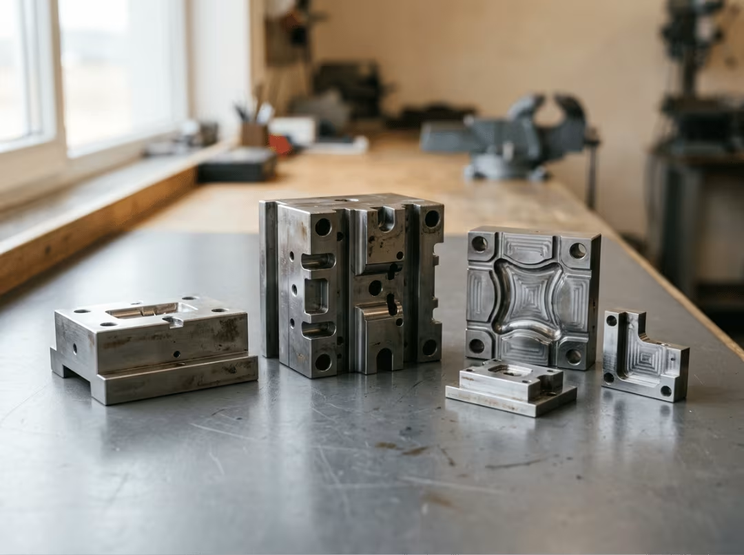
Reach for the higher-grade steel when your resin is abrasive, or your volume is high enough that early wear would cost you more than the better steel ever would.
Common Core and Cavity Defects — and How to Fix Them
Most molding defects trace back to a specific core-or-cavity cause. The trouble is that people reach for a process fix first — adjust pressure, tweak temperature, slow the injection — when the root is actually in the tool or the part design. Knowing which lever to pull saves you from chasing symptoms around the machine all week. Here are the six you’ll meet most often, and where the real fix lives.
Flash
Flash is the thin fin of plastic that squeezes out along the parting line. It usually means the shut-off surfaces aren’t sealing, the clamp can’t hold the mold closed under fill pressure, or you’re overpacking. Worn shut-off faces are a tooling fix — re-fit the parting line. Tonnage is a process fix. And if you’re overpacking to chase a short shot in another section, stop: you’re trading defects. Back off the pressure, check the venting, and find the source of the fill problem.
Short Shots
A short shot is a part that didn’t fill. Flow restriction, trapped air, or insufficient injection pressure are the usual suspects — and most of them respond to process changes: raise the melt temperature, boost injection speed, or increase the injection pressure. But when one cavity fills, and the one next to it starves, that’s a runner-balance problem, and no process tweak fixes an unbalanced runner. If air is trapped in a blind rib, the answer is a vent, not more pressure.
Sink Marks and Voids
Sinks and voids come from thick sections that cool too slowly, insufficient pack pressure, or hot spots in the steel. The instinct is to pile on pack pressure — it sometimes helps a little, and then you move on. The better answer is to design the mass out. Core out the thick boss so the wall thickness becomes uniform, and the sink disappears at its source. We’ve seen stubborn sinks on heavy bosses vanish the moment the section was hollowed, with cycle time dropping as an added benefit. Cranking pressure is treating the symptom; coring the section cures it.
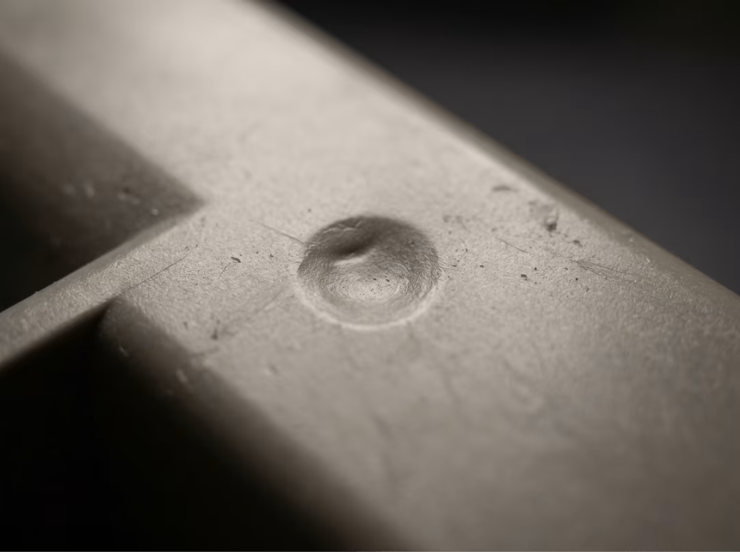
Ejection Marks and Sticking
When a part scuffs, stress-whitens, or won’t leave the core, the cause is almost always insufficient draft, insufficient texture, or an ejector system that’s overmatched for the geometry. More draft is the design fix and the permanent one. On the tooling side, you can add ejector area, polish the core, or switch to air-assisted ejection. A deep, smooth housing that was gripping its core under vacuum came free cleanly once an air poppet was added — a cleaner solution than crowding the part face with extra pins.
Warpage
Warp is uneven shrinkage pulling the part out of flatness. The causes are uneven cooling, unbalanced gates, or different shrink rates across thick and thin sections. Balancing the cooling circuit is the first move. Where a hot spot lingers, conformal channels can reach what straight-drilled lines can’t. Running each mold half at a different temperature is sometimes the only way to even out the shrink when the geometry is asymmetric.
Gate Vestige and Burrs
The leftover nub at the gate and the sharp edge around it stem from the gate geometry and the way the melt tears off at the pack-pressure cutover. Getting it right is a tooling-and-process pairing: choose the right gate style and land length for the part, then tune the holding-pressure profile until the gate freezes clean without leaving a spur that needs manual trimming.
The pattern across all six is the same: fix it in the design when you can, in the tool when you must, and at the press only when the design and tooling are already doing their job.
Working With Your Mold Maker Before Steel Is Cut
The cheapest time to fix a mold is before it exists. Once steel is hardened and machined, every change is slow and expensive — a re-cut, a new insert, a lost week. The conversations you have during the design phase are where the economics of the whole tool get set. A mold maker who catches a draft problem in DFM review hands you a fix that costs nothing. The same problem found at the first tryout costs a re-cut, which you pay for in full.
What to Ask Up Front
Before you commit to a shop, put these questions on the table:
- Do they give real DFM feedback on your geometry? You want a shop that flags thin walls, tight draft, and risky ejection before quoting — not one that cuts exactly what you sent and lets you find the problems at tryout.
- Can they run mold-flow simulation? Simulation verifies gate placement, cooling layout, and packing before a chip is cut. If they can’t run it or won’t, you’re paying for cut-and-try instead.
- Does the quote name steel type, cavity count, and expected cycle time? A serious quote commits to specifics. A vague number leaves you exposed on both quality and cost.
- Have they built similar tools for your resin and industry? A shop that’s run glass-filled nylon or medical-grade parts before already knows the failure modes — you’re not teaching them on your dime.
How to Read a Quote
The lowest number is rarely the cheapest tool. A bargain quote often hides a softer steel grade, a thinner cavity count, or tolerances that start to drift after the first few thousand shots — and you pay the difference later in wear, re-cuts, and piece-price creep.
We’ve seen a “cheap” P20 quote win a job that needed H13. The resin was glass-filled, the tool wore inside the first production run, dimensions drifted, and inserts had to be remachined mid-program. The savings from day one turned into a bigger bill by month three. A real quote breaks out machining, heat treatment, texturing, tryout runs, and engineering tweaks as separate line items — so you can see what you’re actually buying, not just compare headline numbers.
Why Early Collaboration Pays
Small design changes are free on a CAD model. The same changes in hardened steel are expensive and slow. A half-degree of draft, a relocated gate, a wall thinned to cool evenly — trivial before cutting, painful after. Bring your mold maker in before you finalize the geometry, not after, and run prototype and tryout loops while steel is still an idea rather than a sunk cost. When evaluating tooling suppliers, look for shops that treat DFM review as a standard part of the quoting process, not an optional add-on — the kind of precision fabrication capability that separates a real manufacturing partner from a shop that cuts what you send and hands the problems back at tryout. The issues you surface in DFM review are the ones you never pay to fix twice.
Practical Ways to Build a Faster, Cheaper Mold
Mold cost gets controlled in a few specific places: how the melt flows, how mechanically complex the tool is, and how many problems you find before anyone cuts steel. Get those right, and the savings carry through the tool’s entire production life.
Balance the Runner and Gate System
Even fill is what keeps a multi-cavity mold running cleanly. When one cavity fills fast while another starves, you’re fighting the mold on every shot. Balance the runner and gate layout so that every cavity sees the same pressure and flow. The cold-runner versus hot-runner decision comes down to volume and economics: cold runners are cheaper to build and simpler to maintain, but they waste material and add cycle time. Hot runners cost more upfront and require more maintenance, but they reduce waste and shorten cycle times in high-volume programs.
Keep the Tool Simple
Every slide, lifter, and side action adds cost, lead time, and a mechanism that can eventually wear out or fail. Before accepting a complex action, ask whether a smarter parting line would make it unnecessary — a lot of undercuts simply disappear when the part is split differently. Simpler inserts are faster to replace, cheaper to rework, and easier to keep in good condition over a long production run.
Simulate Early, Maintain Consistently
Mold-flow analysis finds fill, cooling, and warp problems before the first chip is cut. The difference between catching a gate location problem in simulation and catching it on the first tryout is the cost of a new insert and two weeks of schedule disruption. Simulation replaces the cut-and-try loop with a plan you can actually trust. When mold inserts require precision rework, CNC machining delivers the accuracy and repeatability that keep dimensions where they need to be.
One habit protects everything downstream: maintenance. Clean the venting and shut-off surfaces on a regular schedule. Re-polish and re-coat wear zones before they start degrading part quality. Store the tool protected between production runs. Cavity surface condition transfers directly to every part the mold produces — for a closer look at how finish standards and surface treatment choices affect that outcome, the CNC machining surface finish guide is a useful reference. A well-maintained mold holds its dimensional performance far longer than a neglected one — and a neglected tool quietly erases every dollar of smart engineering that went into building it.
Frequently Asked Questions
What is the difference between a core and a cavity in injection molding?
The cavity forms the outside of the part; the core forms the inside. The cavity sits on the stationary A-side and controls the exterior surface, appearance, and cosmetic finish. The core sits on the moving B-side, carries the ejector system, and runs hotter than the cavity because the plastic shrinks and grips it as it cools.
Why does the core always form the inside of the part?
Plastic shrinks as it cools and grips whatever surface it wraps around — which is the core. Mounting the core on the moving B-side lets the ejector system push the part free as the mold opens. That’s why internal geometry always lives on the core side: the part has to release from it on every shot.
How much draft angle do I need for my molded part?
Plan for 0.5 to 2 degrees per side as your baseline, with deeper walls requiring more. Textured surfaces need roughly one additional degree of draft for every 0.001 inch of texture depth. Without it, the texture acts as a gripping surface during ejection and drags against the steel.
What are conformal cooling channels, and when are they worth it?
Conformal cooling channels follow the contour of the part rather than running straight through the steel, and they’re typically produced using metal 3D printing. They’re worth the added cost when a hot spot won’t clear with conventional drilled channels, or when cycle time has plateaued, and nothing else is moving it.
What is the best steel for a core in a high-volume production mold?
H13 is the standard choice for high-volume work, especially with abrasive or glass-filled resins. It holds detail and resists wear far longer than pre-hardened P20, which suits low- to medium-volume tools where extreme wear resistance isn’t required.
What is the difference between a two-plate and three-plate mold?
A two-plate mold opens along a single parting line — simpler and less expensive to build. A three-plate mold adds a second parting plane, which gives you more flexibility in gate placement but raises cost and adds mechanical complexity. Use a three-plate only when the gating strategy genuinely requires it.
How do I reduce sink marks on a thick section?
Core out the thick section so the wall stays uniform rather than fighting the sink with pack pressure. Uniform walls cool evenly, which eliminates the sink at its root. As a bonus, removing that mass almost always shortens cycle time too.
How many cavities should my mold have for a given production volume?
Match cavity count to your annual volume target and the cycle time you need to hit output. Higher volumes justify adding more cavities to drive the piece price down; low volumes rarely recoup the added tooling cost. Run the math with your mold maker — more cavities mean a more expensive tool, but the per-part cost drops as volume climbs.
Conclusion
Every good mold comes down to the same split: the core forms the inside, the cavity forms the outside, and all the decisions that determine quality, cycle time, and tooling cost are made long before steel is cut. Draft, cooling, ejection, and shrinkage are the four calls that matter most — and each is easy to change on a model but expensive to fix in a hardened insert.
That’s the thread running through this whole guide. Design the mass out instead of pressuring around it. Add a draft where the part needs to be released. Cool the core hardest, because it runs hottest. And bring your mold maker in early, while a change still costs nothing but a conversation.
The next move is simple: pull up your part model, check wall thickness and draft on every face that has to release, and start talking to a mold maker before anyone touches steel. The problems you solve on paper are the ones you never pay for twice.