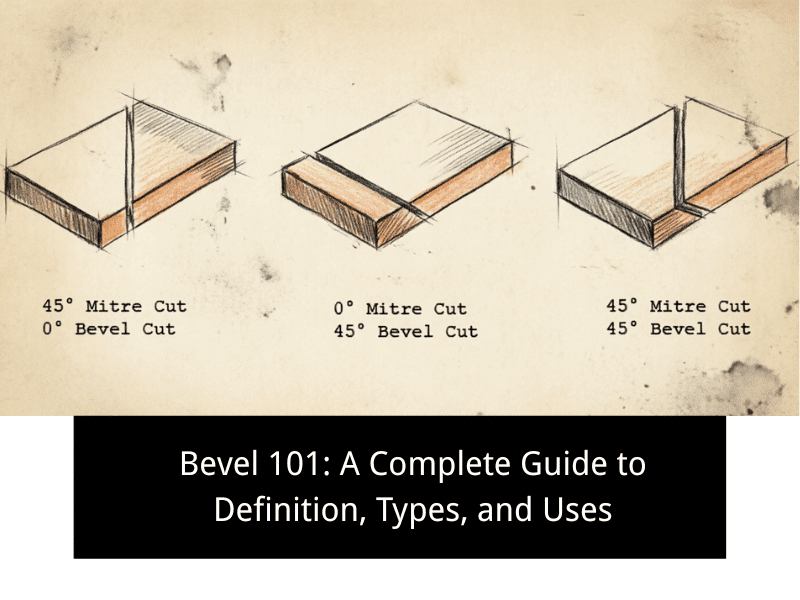
Bevels are everywhere in machining, fabrication, welding prep, and product design, but they are often misunderstood or confused with chamfers, radii, or simple edge breaks. In practice, a bevel is more than a cosmetic edge treatment. It can improve safety, support assembly, prepare surfaces for joining, and help parts perform better under load.
If you work with machined parts, sheet metal, welded structures, CAD models, or technical drawings, understanding bevels will help you make better design and manufacturing decisions. The right bevel can reduce sharp edges, improve fit, and support more reliable production.
In this guide, you will learn what a bevel is, the main types of bevels, how beveling is performed, where beveled holes are used, how bevels compare with similar features, and how bevels are created and defined in CAD and engineering drawings.
1.0 What Is a Bevel?
A bevel is an angled surface created where an original sharp edge, corner, or end face has been cut or formed away. In simple terms, it replaces a square edge with a sloped one. Bevels are used in many industries, including machining, metal fabrication, woodworking, pipe preparation, and mechanical design. They may be applied for function, safety, fit-up, stress control, or appearance, depending on the part and the manufacturing goal.
Geometrically, a bevel is a straight, slanted transition between two surfaces. That makes it similar to a chamfer in many everyday situations, and in casual use, the two terms are sometimes treated as interchangeable. However, in engineering practice, bevels often appear in contexts such as weld prep, edge shaping, end treatment, and hole entry geometry, whereas chamfers are more commonly used for defined edge breaking on machined parts. A bevel also differs from a fillet or radius, which creates a curved transition instead of a flat, angled one.
Bevels are common on metal, plastic, composite, and wood parts. For example, pipe ends are beveled before welding, machine edges are beveled to remove sharp corners, and hole entries may be beveled to guide screws, fasteners, or pins into place.
2.0 Types of Bevels
Bevels can be categorized by geometry, dimensioning method, and intended use. Some are simple and standardized, while others are custom features created for fit, assembly, or weld preparation.
Standard Bevel (45° Equal Distance)
This is one of the most common bevel types. It is formed by removing equal amounts of material from two adjacent faces, usually at a 45° angle. Because the bevel is symmetrical, it is easy to define, machine, inspect, and repeat across batches. This makes it a common choice for machined blocks, brackets, covers, and general-purpose components.
A standard bevel is often used to remove sharp corners, improve handling safety, and create a cleaner appearance. It is also a common default option in many CAD tools because it is easy to model and dimension.
Bevel by Distance and Angle (Custom Angle)
This type is defined by a single linear distance and a single angle, rather than by equal offsets. It allows the designer to control the slope more precisely, which is useful when mating geometry, insertion behavior, or weld prep requirements must be met.
Custom-angle bevels are often used where one specific edge condition matters more than symmetry. You may see them on locating surfaces, lead-ins, alignment features, or parts that need a defined approach angle during assembly.
Asymmetric Bevel (Two-Distance Bevel)
An asymmetric bevel uses different distances on the two adjoining faces. Instead of forming a balanced 45° shape, it creates an unevenly angled face tailored to the available space or functional need.
This type is useful when one side of the part has limited clearance, or when the bevel must favor one direction during insertion, contact, or load transfer. It is common in compact assemblies, specialized fixtures, and custom machine components.
Hole Edge Bevel (Lead-In Bevel)
A hole edge bevel is applied to the entrance of a drilled, bored, or machined hole. Its main purpose is to create a lead-in that helps guide screws, bolts, pins, bushings, or shafts into place. It can also reduce burrs, lower edge damage, and improve the service life of the hole.
Typical callouts include forms such as “C1.0 × 45°” and other dimensional variations, depending on the drawing standards. Hole edge bevels are widely used in threaded holes, locating holes, and hole entries to facilitate assembly.
End Face Bevel
An end face bevel is created around the outer edge of a shaft, tube, rod, pipe, or disc end. It removes the sharp transition at the part end and can support handling, alignment, insertion, or weld preparation.
This type is especially important in shafts and pipe components. On rotating parts, it may reduce edge damage during assembly. On pipes and thick sections, it is often essential to prepare weld joints with proper penetration.
Custom Bevel Profile
Some applications require bevels that go beyond simple equal-distance or fixed-angle forms. These custom profiles may involve compound geometry, varying angles, deeper weld-prep shapes, or surfaces tailored to a specific mating part.
They are common in aerospace parts, pressure components, tooling, medical devices, and high-precision industrial equipment. These bevels are usually defined in CAD and often require CNC machining, multi-axis cutting, grinding, or specialized beveling systems.
3.0 How Is Beveling Performed?
Beveling can be achieved through several manufacturing methods, depending on the part’s shape, material, precision requirements, and production volume. Common approaches include turning, milling, drilling, grinding, and manual edge finishing.
Turning Bevels
Turning is best suited for cylindrical parts such as shafts, bushings, sleeves, and pipe-like components. On a lathe, the workpiece rotates while the cutting tool is fed at a controlled angle to create the bevel.
Common tools include straight-profile turning tools for simple angled bevels and form tools for repeatable end preparation. This method is efficient for high-volume production and for parts where concentricity and consistent edge geometry matter.
Milling Bevels
Milling is widely used for beveling flat surfaces, outer edges, pockets, and contoured features on non-rotating workpieces. A rotating cutter removes material from the selected edge while the workpiece remains fixed or is moved under programmed control.
Common tools include chamfer mills, angle cutters, end mills, and specialty bevel cutters. Milling offers strong flexibility and is often the preferred method for prismatic parts, localized bevel features, and CNC work in which multiple edges must be processed in a single setup.
Drilling Bevels
Drilling-related beveling is usually applied at hole entrances. A larger tool is used to create an angled edge around the opening, either as a lead-in or as part of a hole-finishing operation.
This can be done with countersink tools, center drills, spot drills, or dedicated bevel tools, depending on the required geometry. The method is fast and practical for individual holes, but secondary burrs may still need to be removed, especially in metal parts or threaded hole applications.
Grinding and Manual Beveling
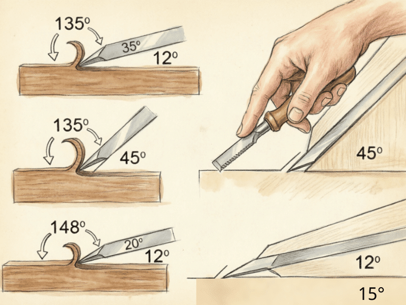
Grinding and manual beveling are often used for weld prep, deburring, repair work, and parts with irregular geometry. Angle grinders, handheld bevelers, files, abrasive wheels, and sanding tools can all be used to create or refine a bevel.
This method is especially common in fabrication shops, field work, and low-volume processing. It offers flexibility and portability, but it is less suitable for tight tolerances unless supported by jigs, fixtures, or skilled operators. For consistent production quality, automated or CNC-based beveling is usually the better choice.
In practice, the best beveling method depends on the balance between speed, accuracy, part geometry, and surface finish requirements.
4.0 What Is a Beveled Hole and How Is It Defined?
A beveled hole is a hole whose entrance edge has been cut at an angle rather than left as a sharp 90-degree intersection. This angled entry improves function in several ways. It can guide fasteners or pins into place, reduce burr-related interference, protect the edge from chipping, and lower stress concentration around the opening.
Beveled holes are widely used in threaded holes, locating holes, bushing seats, and holes intended for repeated assembly. In many cases, the bevel acts as a lead-in feature. This makes it easier to start screws, dowels, shafts, or mating parts without catching on a sharp edge.
In technical drawings, beveled holes are commonly defined by a size and angle. Example notations include:
- C1.0 × 45°
- 2 × 45°
- 0.5 mm × 30°
The exact notation style depends on company practice and drafting standard, but the design intent is the same: define the angled edge clearly enough for machining and inspection. In precision manufacturing, this simple feature can improve assembly speed, protect threads, and increase the reliability of the finished part.
5.0 Bevel vs. Radius: What’s the Difference?
In part design and machining, bevels and radii are both used to remove sharp edges. They may serve similar goals, but they are not the same feature. A bevel creates a flat angled surface, while a radius creates a curved transition.
Geometry
A bevel is straight and angular. It is usually defined by angle and distance, or by two distances. A radius, also called a fillet in many cases, is rounded and defined by a radius value such as R1.0 or R3.0.
Application Areas
Bevels are common on hole entries, outer edges, weld-prep zones, pipe ends, and alignment features. Radii are common where smoother stress flow, softer appearance, or easier cleaning is needed, such as external corners, molded parts, and blended transitions.
Machining Methods
Bevels are often easier and faster to produce using milling, turning, drilling, grinding, or manual beveling. Radii may require form tools, corner-rounding cutters, CNC contouring, or molding processes, depending on the part shape.
| Comparison Item | Bevel | Radius / Fillet |
|---|---|---|
| Geometry | Straight-angled surface | Curved transition surface |
| Typical Definition | Distance + angle, or two distances | Radius value |
| Common Use Areas | Hole entries, edges, weld prep, alignment | Corners, blends, stress reduction zones |
| Main Purpose | Edge removal, assembly aid, prep work | Smooth transition, lower stress concentration |
| Machining Methods | Turning, milling, drilling, grinding | CNC contouring, corner rounding, molding |
| CAD Notation | C1.0 × 45°, 2 × 30° | R1.0, R2.5 |
In short, a bevel is best when you need a controlled angled edge, while a radius is better when you need a smooth curved transition.
6.0 Why Is Beveling Important?
Beveling is not just an edge-finishing step. In many parts, it directly affects safety, fit, durability, and manufacturing performance.
Improved Safety
Sharp machined or cut edges can cause cuts during handling, assembly, transport, or service. Beveling removes sharp corners, making parts safer to touch, install, and maintain.
Simplified Assembly
A bevel often acts as a guide surface. It helps screws, shafts, pins, bushings, and mating components enter more easily, reducing alignment problems and speeding up assembly.
Reduced Stress Concentration
Sharp corners can act as stress risers under load, impact, or vibration. A bevel softens that transition and can help distribute force more evenly, especially around hole entries, edges, and joined surfaces.
Enhanced Durability and Mechanical Integrity
Unprotected sharp edges are more likely to chip, crack, burr, or wear during use. A beveled edge is less fragile and can withstand repeated contact, handling, and assembly cycles more effectively.
Optimized Joint Performance
In welding, bevels are often essential. They prepare edges for better weld access and penetration. In bolted or assembled joints, bevels improve mating conditions and reduce interference at the entry point.
Increased Manufacturing Efficiency
Bevels can be standardized and programmed into CNC operations, reducing manual finishing and improving consistency. In production environments, that means faster throughput, less rework, and more predictable results.
The key takeaway is simple: beveling improves both the part and the process. It supports safer handling, easier assembly, and more reliable manufacturing outcomes.
7.0 Common Beveling Tool Categories & Application Guide
Beveling tools vary widely depending on whether the goal is weld prep, edge conditioning, hole entry treatment, or precision machining. The main categories below cover the most common production and fabrication scenarios.
Beveling Machines
Bench-top beveling machines are used for flat bars, plates, and smaller production parts where repeatability matters. Handheld beveling machines are useful for repair work, irregular geometry, and on-site jobs. Pipe beveling machines are designed for internal, external, and face beveling on tube and pipe ends, especially before welding. Double-end beveling machines are used to process rods and tubes that require fast, accurate end prep on automated lines.
CNC Beveling Tools
For CNC lathes and machining centers, beveling is often done with chamfer inserts, angle tools, chamfer end mills, and form tools. These tools are well-suited for continuous, repeatable bevel production. Center drills and spot drills may also create lead-in bevels around holes. In high-precision applications, custom tooling may be used for special bevel geometry or multi-feature operations.
Manual & Lightweight Beveling Tools
For lighter work, repair, and finishing, manual beveling tools remain useful. Deburring blades, hand bevel knives, files, angle grinders, flap discs, and abrasive stones can all create or refine bevels. These tools work well for small batches, maintenance jobs, and localized edge treatment. They are flexible and inexpensive, though less consistent than CNC or dedicated machine solutions.
Beveling Attachments for Laser/Plasma/Waterjet Cutting
Automated cutting systems may include bevel-capable heads that tilt during cutting. Laser bevel heads can produce angled edges for part prep and weld joint geometry. Plasma bevel cutting systems are widely used for structural steel and fabrication work. Multi-axis waterjet heads can also create accurate bevels through controlled nozzle orientation. These systems are valuable when cutting and beveling need to be performed in a single operation.
Recommended Accessories & Tool Pairings
Angle grinder users often pair beveling with flap discs, grinding discs, or carbide burrs, depending on the material and target finish. Straight flap discs are useful for flat edges, while shaped abrasive tools are better for contours and corners. For pneumatic or die grinders, carbide burrs are a common choice for aggressive removal and weld prep. Coolant-compatible abrasives are helpful when working with nonferrous metals where heat discoloration must be minimized.
The right tool category depends on the material, accuracy target, production volume, and whether the bevel is a design feature, a weld-prep feature, or a finishing step.
8.0 Tool Selection Guide (By Application Scenario)
| Application Need | Recommended Tool Type |
|---|---|
| Pipe end weld preparation | Pipe beveling machine, portable pipe beveler |
| CNC-machined edges | Chamfer end mill, bevel insert, angle tool |
| Hole entry beveling | Countersink, spot drill, center drill |
| Flat plate edge beveling | Bench-top beveling machine, milling cutter |
| Structural steel bevel cutting | Plasma bevel head, laser bevel cutting system |
| Irregular edges or field repair | Handheld beveling tool, angle grinder, file |
| High-volume automated production | CNC tooling system, servo-driven beveling machine |
| Light deburring plus small bevels | Manual deburring tool, bevel knife, abrasive wheel |
This guide helps match the tool to the part, which is usually the fastest way to improve both quality and efficiency.
9.0 What Is a Beveled Edge in CAD?
In CAD, a beveled edge is an angled transition created between two intersecting faces by removing the original sharp edge. It is used to represent a real manufactured feature and to communicate how the part should function, assemble, and be machined. A beveled edge in CAD may be used for safety, fit, weld prep, visual realism, or manufacturing clarity.
Most mainstream CAD systems allow bevel-like features to be created using chamfer tools, edge-modification tools, or custom modeled surfaces. The common definition methods are equal distance, distance and angle, and two-distance input. These methods let the designer control whether the bevel is symmetric or asymmetric.
In 3D models, bevels help clearly define the final part geometry. In 2D drawings, they are translated into dimensional callouts, so machinists and inspectors can manufacture and verify the feature correctly. This is especially important when the bevel affects assembly, hole entry, or welding performance rather than serving as a simple cosmetic edge condition.
10.0 How to Create Bevels in CAD
In CAD platforms such as SolidWorks, Fusion 360, Inventor, and similar systems, bevels are commonly created using the chamfer feature or a custom modeled cut. The best method depends on how the bevel is defined on the drawing and how much control the designer needs.
Equal Distance Bevel (Symmetric)
This method is used when the bevel removes the same amount from both adjoining faces. It is the simplest and most common option for standard edge bevels.
Steps:
- Open the bevel or chamfer tool from the features or modify menu.
- Select the target edge.
- Enter the same offset distance for both faces.
- Preview the feature and confirm the operation.
Distance and Angle Bevel
This method is used when the bevel must follow a specific angle and a defined offset. It is useful for assembly lead-ins, pipe-end prep, and controlled edge geometry.
Steps:
- Launch the bevel or chamfer command.
- Select the edge to modify.
- Set the linear distance value.
- Enter the required angle, such as 30°, 45°, or 60°.
- Confirm the preview and apply the feature.
Two-Distance Bevel (Asymmetric)
This method is used when the bevel must be removed in different amounts from the two adjoining faces. It is ideal for space-limited designs and custom part geometry.
Steps:
- Open the bevel or chamfer tool.
- Select the relevant edge.
- Enter one distance for the first face and a different distance for the second face.
- Review the preview to confirm the direction and geometry.
- Apply the feature.
In more advanced designs, bevels may also be created with sweeps, lofts, or multi-axis cuts when the profile is nonstandard. The important part is making sure the CAD feature matches the manufacturing intent and the drawing callout.
11.0 Bevel vs. Break Edge
A break edge is usually a very small edge treatment used only to remove sharpness or burrs. It is often not tightly controlled and may be noted with general instructions such as “break all sharp edges” or “remove burrs.” A bevel, by contrast, is typically a defined geometric feature with a specified size and angle.
This means a bevel has a functional design role, while a break edge is often a general finishing requirement. A bevel may support assembly, welding, or fit. A break edge mainly improves handling safety and basic edge condition.
| Comparison Item | Bevel | Break Edge |
|---|---|---|
| Purpose | Functional angled feature | Remove sharpness or burrs |
| Dimensional Control | Usually specified | Often general or unspecified |
| Geometry | Defined angled surface | Very small, softened edge |
| Typical Use | Assembly, weld prep, edge design | Safety, handling, deburring |
12.0 Bevel vs. Countersink
A bevel and a countersink both involve angled surfaces, but they are used in different ways. A bevel can appear on many outer or inner edges and serves a variety of purposes, such as edge conditioning, alignment, and weld prep. A countersink is a specific conical feature made inside a hole, usually to seat a flat-head fastener.
In other words, all countersinks are angled hole features, but not all beveled hole edges are true countersinks. The difference comes down to design intent, geometry, and standardization.
| Category | Bevel | Countersink |
|---|---|---|
| Function | Edge treatment, guidance, prep | Seat flat-head screw flush |
| Location | Any edge or end | Inside a hole |
| Geometry | Simple angled face | Conical recess |
| Common Angles | 30°, 45°, 60°, custom | 82°, 90°, 100°, standard-based |
| Typical Callout | C1.0 × 45° | Ø8 × 90° countersink |
13.0 Bevel vs. Deburring
Beveling and deburring both improve edge condition, but they are not the same process. Beveling creates a deliberately angled surface with defined geometry. Deburring removes unwanted burrs, sharp fragments, or roughness left by machining, cutting, or drilling.
A part may be deburred without receiving a true bevel, and a part may be beveled but still need deburring afterward if burrs remain. In production, the two operations are often related but should not be confused.
| Category | Bevel | Deburring |
|---|---|---|
| Definition | Defined angled edge feature | Removal of burrs and sharp remnants |
| Control | Dimensioned and intentional | Process-driven, often less defined |
| Purpose | Function, fit, safety, prep | Cleanliness, safety, finish quality |
| Common Methods | Milling, turning, grinding, CNC | Filing, brushing, grinding, tumbling |
14.0 What Is a Bevel in Engineering?
In engineering, a bevel is a deliberately specified angled surface used to replace a sharp edge or prepare a part for function, assembly, or joining. It is not just a visual feature. It may affect stress behavior, weld access, fastener guidance, part fit, and inspection requirements. Unless otherwise specified, common bevel angles are often based on design practice, manufacturability, or relevant industry standards.
Engineers use bevels to eliminate sharp corners, improve safety, guide mating parts, and optimize edge conditions for welding, bonding, or assembly. In pressure piping and structural fabrication, bevel geometry can directly affect weld penetration and joint quality. In machined components, bevels often support reliable insertion and reduce the risk of edge damage.
In technical drawings, bevels should be clearly dimensioned and interpreted in accordance with recognized engineering and drafting standards. Depending on the application, standards and practices may reference systems such as ASME Y14.5, ISO 13715, and related manufacturing specifications. Clear bevel definition improves consistency between design, machining, inspection, and final performance.
A well-defined bevel is a small feature, but in engineering, it can have a major impact on quality, safety, and manufacturability.
Conclusion
Bevels play an important role in machining, fabrication, CAD design, and engineering practice. They help remove sharp edges, support easier assembly, improve durability, prepare joints, and make parts safer and more reliable. Once you understand the different bevel types, machining methods, tool options, and drawing definitions, it becomes much easier to choose the right edge treatment for the job. Whether you are designing a part, preparing pipe for welding, or programming a CNC operation, a well-specified bevel can improve both the product and the process.